
Overview
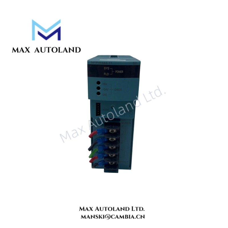
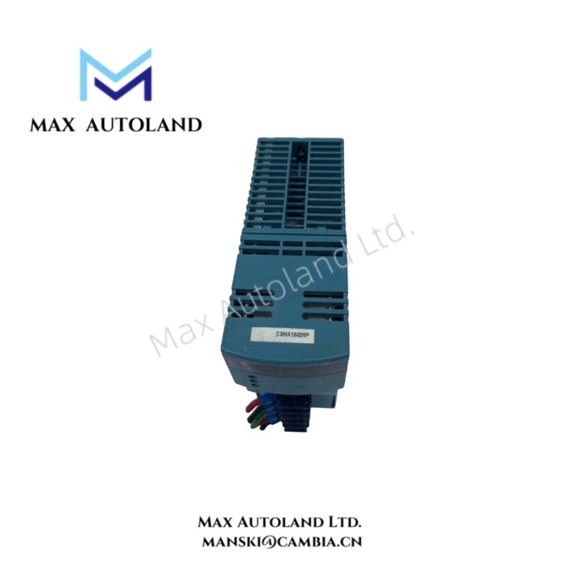
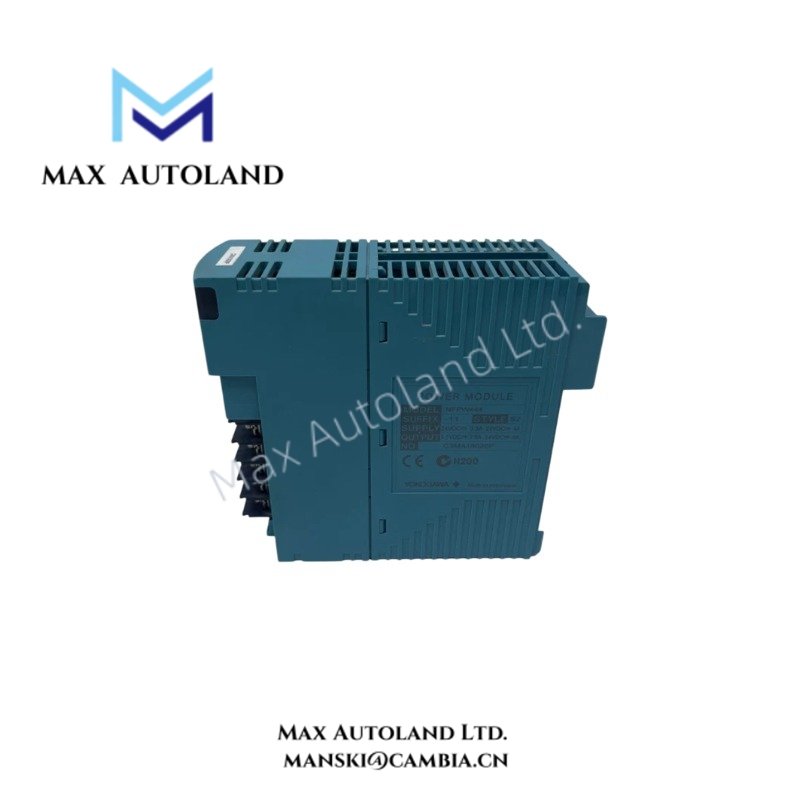
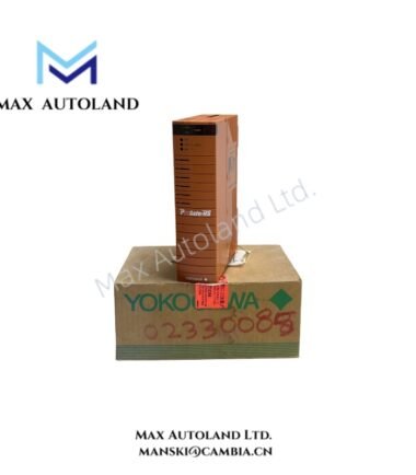
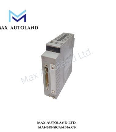
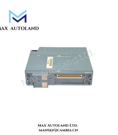
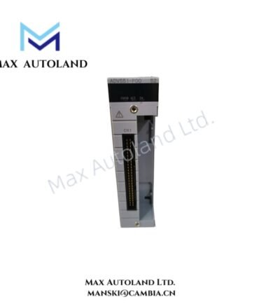
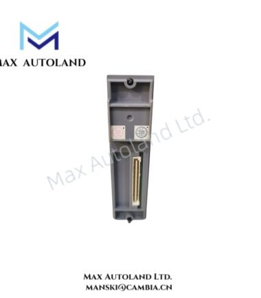
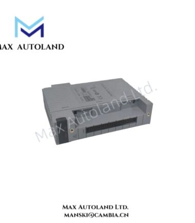
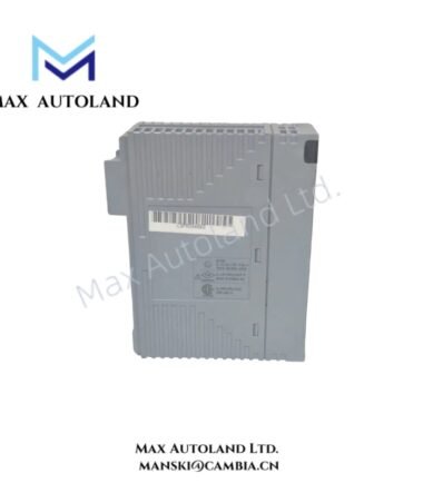
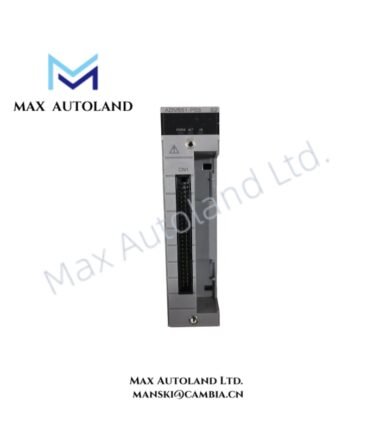
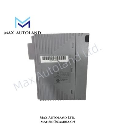
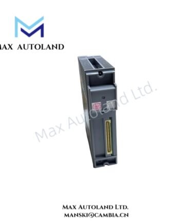
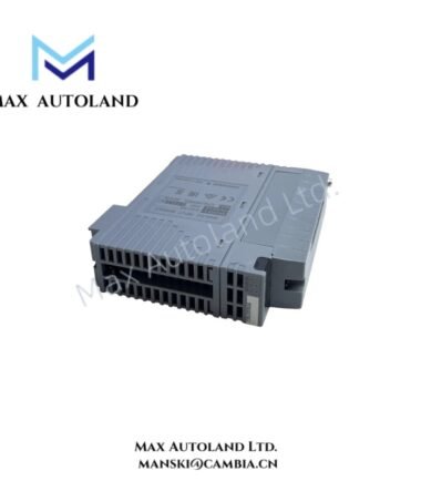
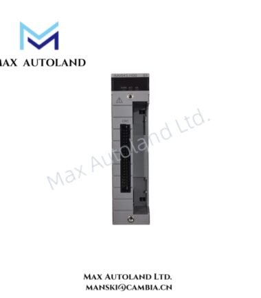
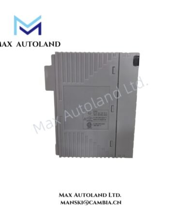
Configured for supplying regulated DC power in the FCN-100 controller system, the Yokogawa NFPW444-50 (NFPW444 Power Supply Module) provides direct electrical power conversion from a 24 V DC input to a +5.1 V DC output. The module accepts 21.6 to 31.2 V DC input voltage and supplies up to 7.8 A output current for compatible FCN-100 system hardware.
Suffix Breakdown & Model Matrix
The provided model information identifies NFPW444-50 as a standard, non-explosion-protected basic type.
| Code | Specification |
|---|---|
| NFPW444 | Power Supply Module with 24 V DC input |
| 5 | Standard type with no explosion protection |
| 0 | Basic type |
The supplied information also references 1S as a configuration designation for a 1-phase version used with a 1-phase load between two phases or with one phase connected to the neutral phase. This designation is not presented as part of the NFPW444-50 suffix breakdown.
Hardware Specifications
| Parameter | Specification |
|---|---|
| Model | NFPW444-50 |
| Base Model | NFPW444 |
| Brand | Yokogawa |
| Origin | Not specified in the provided data |
| Product Type | Power Supply Module |
| Input Type | 24 V DC |
| Rated Input Voltage | 24 V DC |
| Input Voltage Range | 21.6 to 31.2 V DC |
| Rated Output Voltage | +5.1 V DC |
| Rated Output Current | 0 to 7.8 A |
| Weight | Approx. 0.6 kg |
| Dimensions | Approx. 146.5 x 49.7 x 130 mm |
| System Platform | Yokogawa FCN-100 |
| Supported System Components | Base Module, CPU Module, SB Bus Repeat Module, I/O Modules |
| Cooling Arrangement | Low heat dissipation supports fanless controller configurations |
| System Diagnostics | CPU self-diagnostics, temperature monitoring, and I/O diagnostics |
| Redundancy Support | CPU, power supply module, SB bus, and control network can be duplexed |
| Module Replacement | System architecture supports hot-swappable modules |
FOUNDATION Fieldbus and Process Control Connectivity
The NFPW444-50 operates as part of the Yokogawa FCN-100 controller architecture, which supports process control communication functions. In applicable FCN-100 configurations, the controller can function as a Link Active Scheduler for low-speed voltage mode H1 FOUNDATION Fieldbus segments.
The system can therefore schedule communication on compatible FOUNDATION Fieldbus H1 segments and link with FOUNDATION Fieldbus-enabled field devices. This capability belongs to the supported FCN-100 system architecture rather than being an independent communication interface function of the NFPW444-50 power supply module.
The FCN-100 configuration can also include an SB bus repeat module. The repeat module extends the SB bus, which serves as the local bus for FCN hardware, and allows connection to extension units.
Two base module configurations are identified for the system:
- NFBU200 long base module: Supports connection of up to 2 extension units for I/O expansion.
- NFBU050 short base module: Supports a compact one-unit configuration.
Frequently Asked Questions
Q: What input voltage does the Yokogawa NFPW444-50 accept?
A: The NFPW444-50 has a rated input voltage of 24 V DC and accepts an input voltage range from 21.6 to 31.2 V DC.
Q: What output does the Yokogawa NFPW444-50 provide?
A: The module provides a rated output voltage of +5.1 V DC with a rated output current range of 0 to 7.8 A.
Q: Can the NFPW444-50 operate in a redundant FCN-100 configuration?
A: The provided system information states that the FCN-100 architecture can duplex the CPU, power supply module, SB bus, and control network. Actual redundancy configuration depends on the installed FCN-100 hardware arrangement.
Field Installation Guidelines
- Verify that the external DC supply voltage remains within the specified 21.6 to 31.2 V DC input range.
- Isolate the external power source according to site electrical procedures before installing or removing the module.
- Install the NFPW444-50 only in a compatible Yokogawa FCN-100 hardware configuration.
- Confirm correct module alignment and complete connector engagement before applying system power.
- Keep power wiring separated from high-energy switching conductors where practical to reduce conducted electrical interference.
- Follow the system grounding and shielding requirements specified for the FCN-100 installation.
- Inspect controller diagnostics after installation or replacement to confirm normal power and system status.
- Follow the applicable Yokogawa procedure when installing the module in a duplex or hot-swappable system configuration.
Emerson Top Products
| Emerson DeltaV | Epro | Ovation/Westinghouse |
| KJ1501X1-BC3 | 9100-00049-03 | 1C31122G01 |
| KJ3202X1-BA1 | A6110 | 1C31125G03 |
| KJ3222X1-BA1 | A6120 | 1C31232G01 |
| KJ3243X1-BA1 | A6125 | 1C31147G01 |
| KJ3002X1-BG1 | A6140 | 1B30035H01 |
| KJ3002X1-BB1 | A6210 | 1B30023H02 |
| KJ3001X1-BB1 | A6220 | 1B30023H01 |
| KJ3002X1-BC1 | A6312 | 1C31132G01 |
| KJ3002X1-BF1 | A6312/06 | 1C31129G03 |
| KJ3001X1-BJ1 | A6312/08 | 5X00119G01 |
Reviews
There are no reviews yet.