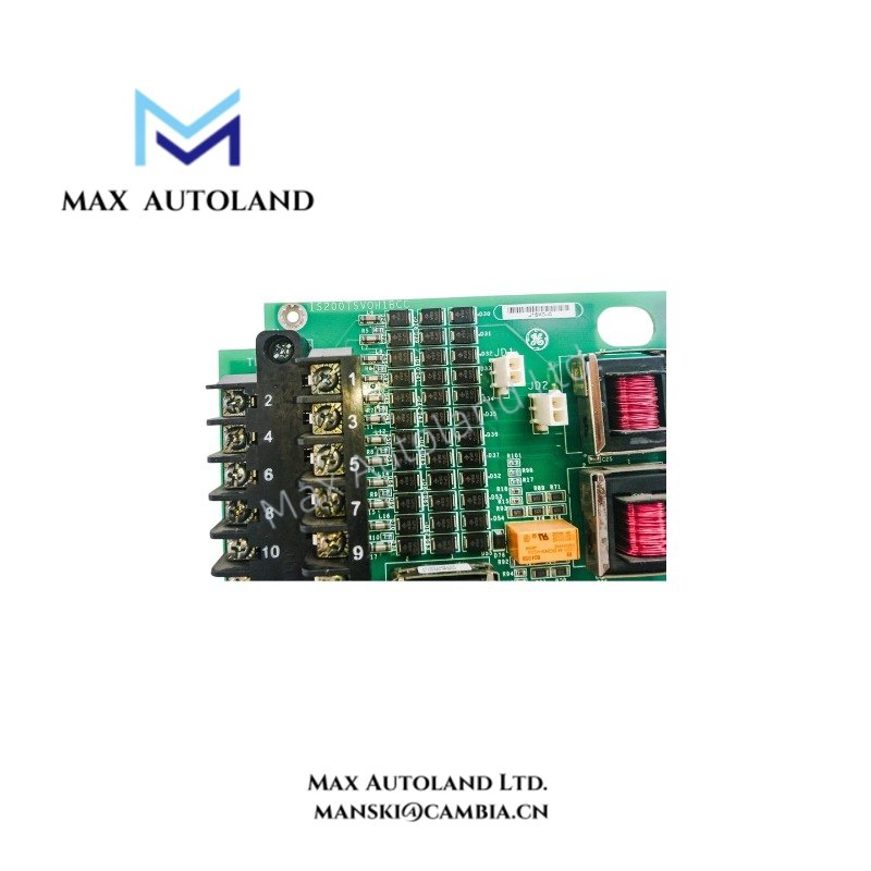
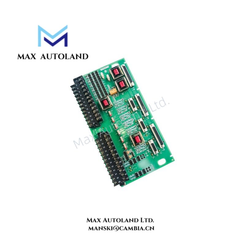

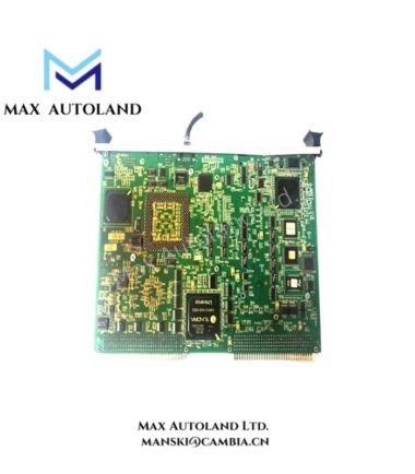
Overview
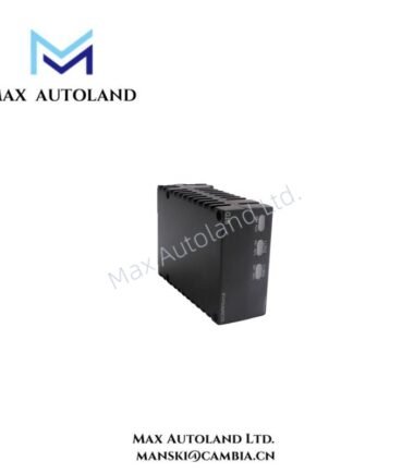
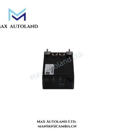
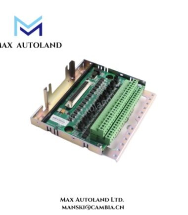
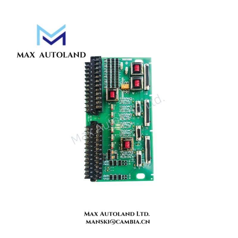
The GE IS200BAPAH1AGD, associated with the base model IS200BAPAH1A, is identified in the supplied description as a Bridge Analog Processor (BAPA) board for the GE Mark VI control platform. The provided information does not confirm its detailed signal ranges, channel count, or electrical ratings. Verify the board identification and hardware revision before installation or replacement.
Hardware Specifications
| Parameter | Specification |
|---|---|
| Model | IS200BAPAH1AGD |
| Base Model | IS200BAPAH1A |
| Brand | General Electric (GE) |
| Product Series | Mark VI |
| Product Type | Bridge Analog Processor Board |
| Functional Classification | Analog Processor / Interface Board |
| Origin | United States |
| Communication Interface | Internal system interface; protocol and bus specifications not provided |
| Tariff Code | 8537101190 |
Backplane Communication and Hardware Compatibility
The supplied description identifies the IS200BAPAH1AGD as an analog processing and interface assembly. However, it does not establish the exact backplane protocol, analog input or output configuration, channel isolation, or controller compatibility.
For GE Mark VI installations, confirm the board’s complete part number, revision, connector arrangement, and corresponding hardware documentation. Do not assume compatibility with Mark VIe solely because both platforms belong to the GE turbine control product family.
Frequently Asked Questions
Q: Can the IS200BAPAH1AGD be replaced directly with an IS200BAPAH1A?
A: Direct replacement compatibility has not been established by the supplied information. Check the complete ordering code, assembly revision, firmware requirements where applicable, and the equipment bill of materials before substitution.
Q: What power supply and backplane current does this board require?
A: The required supply rails and backplane current consumption are not specified in the available data. Obtain the applicable GE hardware manual or electrical drawings before connecting the board.
Q: Does the board support hot swapping?
A: Hot-swap capability is not confirmed. Follow the applicable GE maintenance procedure and isolate power as required before removing or installing the assembly.
Field Installation Guidelines
- Verify identification: Compare the complete board part number and revision with the equipment documentation.
- Isolate the equipment: Follow the approved shutdown, electrical isolation, and lockout/tagout procedures before handling the assembly.
- Inspect connectors: Check connector contacts, board edges, and mounting hardware for contamination, corrosion, or physical damage.
- Control electrostatic discharge: Use an approved ESD wrist strap and grounded workstation when handling the circuit board.
- Check wiring and grounding: Follow the original cabinet drawings for signal routing, cable shielding, and grounding. Do not introduce additional shield-ground connections without confirming the grounding design.
- Verify compatibility: Confirm the correct rack position, mating connectors, power requirements, and supported system configuration before installation.
- Perform functional checks: After installation, follow the approved commissioning procedure and verify controller diagnostics and relevant signal readings before returning the equipment to service.