
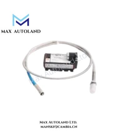
Overview
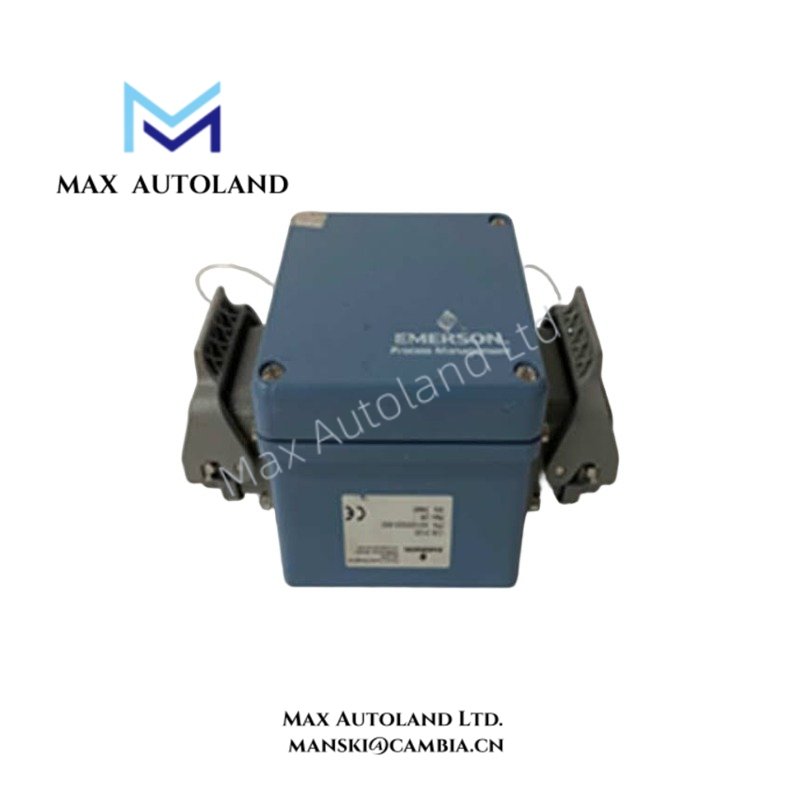
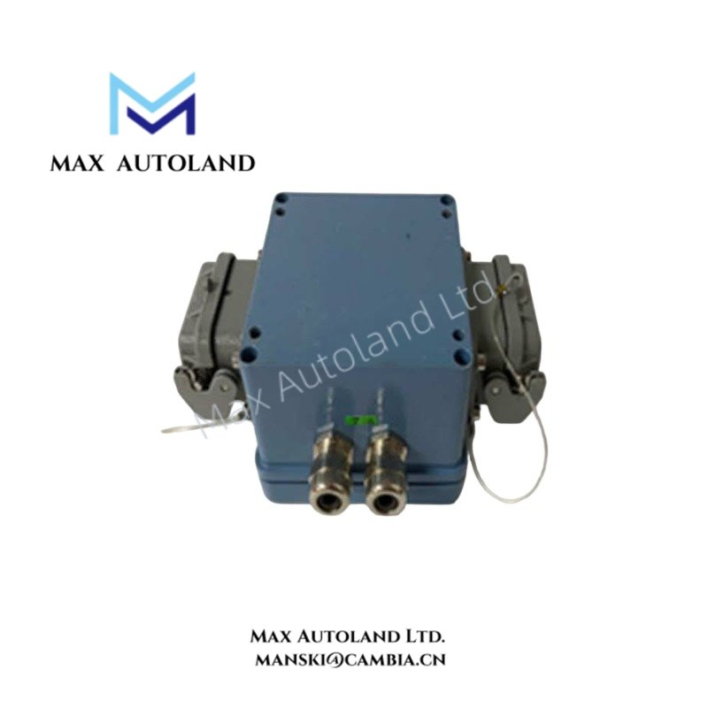
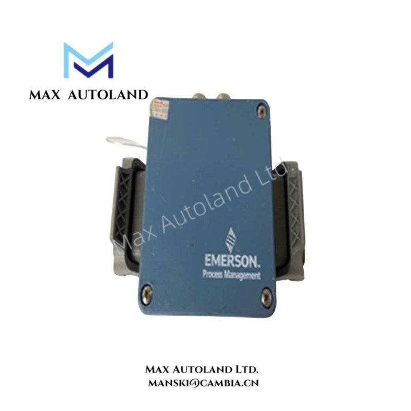
The Emerson EPRO A3120/022-000, also identified by the CSI3120 base model, processes seismic sensor signals for continuous bearing vibration monitoring. It measures vibration velocity through compatible seismic transducers and provides monitoring signals for machinery condition assessment. The unit supports two measurement channels for monitoring vibration at separate machine locations.
Hardware Specifications
| Parameter | Specification |
|---|---|
| Model | A3120/022-000 |
| Base Model | CSI3120 |
| Brand | Emerson EPRO |
| Product Type | Dual-Channel Bearing Vibration Monitor |
| Operating Temp | -20 to +65 deg C (housing variant dependent; verify exact configuration) |
| Measurement Channels | 2 |
| Primary Function | Seismic vibration measurement and monitoring |
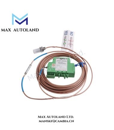
| Sensor Input | Compatible seismic vibration sensors; PR9268 series listed in supplied data |
| Measured Quantity | Vibration velocity |
| Measurement Representation | Peak or RMS, depending on configuration |
| Measuring Range | Configurable; supplied data states up to 0 to 100 mm/s peak |
| High-Pass Filter | 5 Hz, 10 Hz, or 15 Hz |
| Low-Pass Filter | 50 Hz to 1500 Hz |
| Frequency Response | Approximately 4.5 Hz to 1000 Hz, +/- 3 dB |
| Output Signal | 4-20 mA analog output; exact output configuration requires verification |
| Supply Voltage | 12 to 30 VDC |
| Measurement Accuracy | Typically +/- 2% of full scale; confirm against the applicable datasheet |
| Electrical Connection | Harting socket or DIN 43650 connector, depending on version |
| Housing Protection | IP65 for the specified industrial enclosure version |
| Approvals | CE; ATEX/IECEx options require confirmation for the exact variant |
Seismic Signal Processing and Analog Output
The CSI3120 receives vibration signals from compatible seismic transducers and processes them for machinery monitoring. Its two measurement channels support vibration measurement at separate bearing locations or measurement axes, subject to the installed sensor arrangement.
The measurement configuration determines the selected range, signal filtering, and vibration representation. The supplied specifications identify peak and RMS velocity measurement, together with selectable high-pass filtering and an adjustable low-pass range.
The 4-20 mA output provides an analog representation of the configured measurement for connection to a compatible monitoring or control input. However, the exact channel-to-output mapping, loop wiring arrangement, and output isolation characteristics must be verified against the applicable A3120/022-000 documentation.
For process instrumentation integration, confirm the receiving input’s electrical characteristics and scaling before commissioning. Do not assume HART communication or channel-to-channel isolation without model-specific documentation.
Frequently Asked Questions
Q: Which sensor type is compatible with the Emerson EPRO A3120/022-000?
A: The supplied information identifies seismic vibration sensors, including the EPRO PR9268 series. Confirm the sensor’s electrical characteristics and calibration requirements before connecting it.
Q: Does the CSI3120 provide vibration velocity in peak and RMS formats?
A: The supplied specifications identify both peak and RMS measurement, depending on configuration. Verify the selected measurement mode and output scaling before connecting the analog signal to a monitoring system.
Q: What supply voltage does the A3120/022-000 require?
A: The supplied operating range is 12 to 30 VDC. Confirm the terminal assignment and loop wiring arrangement using the documentation for the exact hardware version.
Field Installation Guidelines
1. Verify the hardware: Confirm the complete A3120/022-000 model designation, connector type, enclosure version, and applicable installation documentation before mounting.
2. Inspect the sensor interface: Check the seismic sensor cable, connector condition, and electrical compatibility before connecting the measurement channels.
3. Mount the equipment: Secure the monitor and associated sensors using the installation provisions specified by the manufacturer. Avoid unsupported mounting arrangements or mechanical stress on connectors.
4. Route signal wiring: Separate low-level sensor wiring from motor power cables, variable-frequency drive outputs, and other high-interference conductors where practical.
5. Manage cable shielding: Apply the grounding and shield termination method specified by the equipment documentation and plant instrumentation standards. Avoid creating unintended ground loops.
6. Verify power supply: Confirm that the supply remains within the specified 12 to 30 VDC range under operating conditions.
7. Check analog output scaling: Verify the configured measurement range, output representation, and receiving-system scaling before enabling operational monitoring.
8. Validate measurement response: Compare the monitor output against an appropriate reference measurement or commissioning procedure. Confirm channel assignment and alarm configuration before placing the system into service.
9. Confirm environmental suitability: Check the exact enclosure rating, operating temperature limits, and hazardous-area approvals where applicable. Do not assume that all A3120 variants share identical certifications.


Reviews
There are no reviews yet.