
Overview
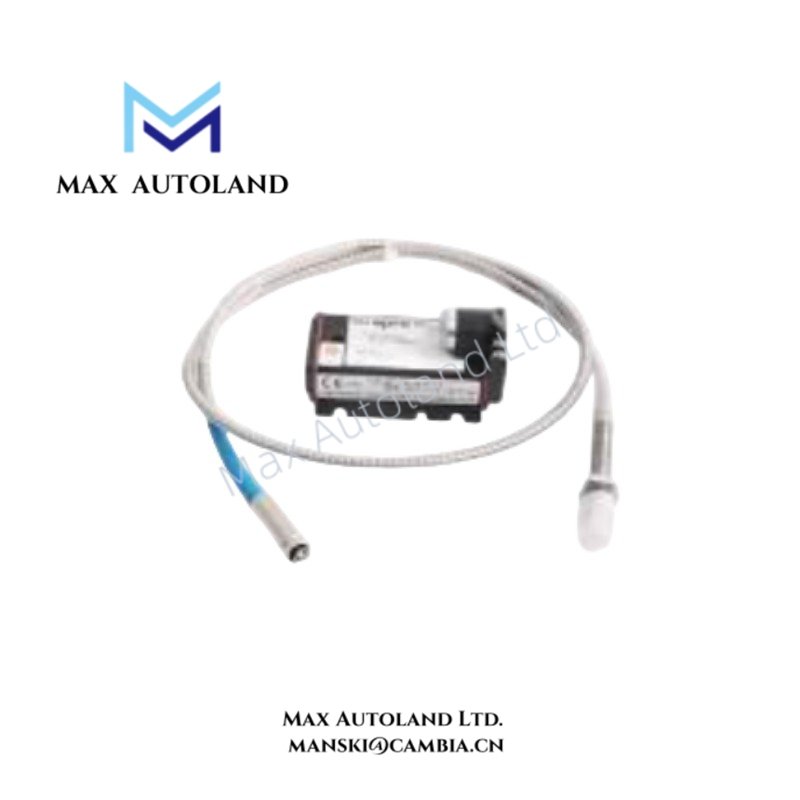
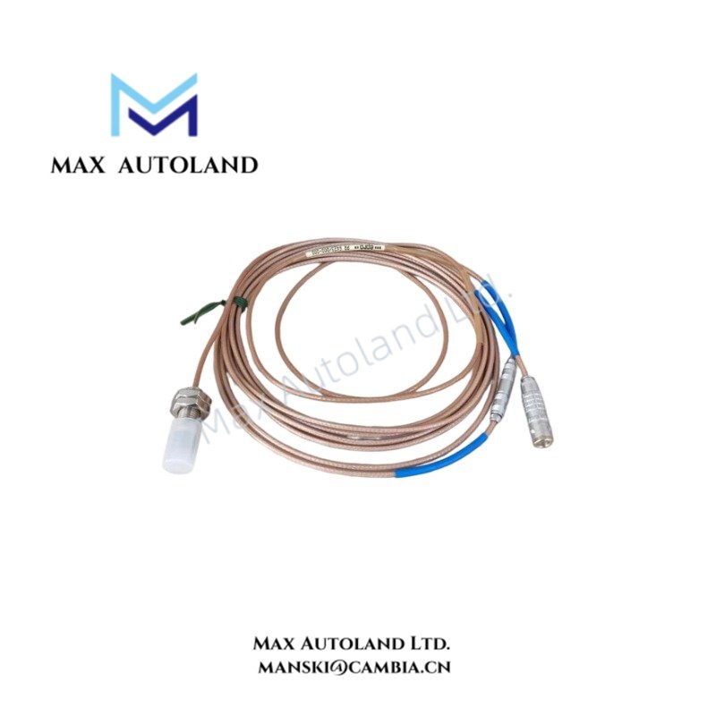
The Emerson EPRO PR6423/000-001-CN, also cataloged under the PR6423 series, operates as an 8 mm non-contact eddy current displacement sensor for measuring shaft position, vibration, eccentricity, and rotational motion. It converts changes in the electromagnetic coupling between the probe tip and a ferromagnetic target into an electrical measurement signal for turbomachinery monitoring systems.
Hardware Specifications
| Parameter | Specification |
|---|---|
| Model | PR6423/000-001-CN |
| Base Model | PR6423 |
| Brand | Emerson EPRO |
| Product Type | 8 mm Eddy Current Proximity Sensor |
| Weight | Approx. 100 g with 1 m cable |
| Dimensions | M10 x 1 sleeve thread; complete dimensions not specified |
| Operating Temp | Sensor and 1 m cable: -35 to +180 deg C |
| Linear Measurement Range | 2 mm (80 mils) |
| Initial Air Gap | 0.5 mm (20 mils) |
| Incremental Scale Factor | 8 V/mm (203.2 mV/mil) +/- 5% |
| Scale Factor Temperature Range | 0 to +45 deg C |
| Linearity Deviation | +/- 0.025 mm (+/- 1 mil) |
| Minimum Shaft Diameter | 25 mm |
| Target Material | Ferromagnetic steel |
| Standard Target Material | 42CrMo4 / AISI 4140 |
| Sensor Tip Material | PEEK |
| Housing Material | Stainless steel |
| Cable Material | PTFE |
| Cable Length | 1 m |
| Protection Rating | IP66, IEC 60529 |
| Measurement Applications | Radial displacement, axial displacement, shaft vibration, eccentricity, and speed |
Eddy Current Measurement and Signal Characteristics
The PR6423/000-001-CN uses an electromagnetic field to detect changes in the distance between the sensor tip and a conductive ferromagnetic target.
As the shaft moves, the probe detects variations in electromagnetic coupling. Consequently, the measurement system converts these variations into displacement-related electrical signals.
The specified incremental scale factor is 8 V/mm, with a tolerance of +/- 5% within the stated temperature range of 0 to +45 deg C.
For accurate measurement, technicians should verify the target material, initial air gap, probe orientation, and compatibility with the connected signal conditioning electronics.
The 2 mm linear measurement range defines the stated displacement range. Meanwhile, the +/- 0.025 mm linearity deviation specifies the maximum deviation from the best-fit straight line.
Frequently Asked Questions (FAQ)
Q: Can the PR6423/000-001-CN measure shaft vibration without physical contact?
A: Yes. The sensor uses eddy current measurement to detect dynamic shaft displacement without mechanical contact between the probe tip and the target surface.
Q: What target material does this sensor require for its specified measurement characteristics?
A: The specified target is ferromagnetic steel, with 42CrMo4 / AISI 4140 identified as the standard material. Different target materials may affect measurement characteristics.
Q: Does the sensor provide a direct measurement signal without external electronics?
A: The sensor operates as part of an eddy current measurement system. Compatible signal conditioning electronics are required to process the probe signal for monitoring applications.
Field Installation Guidelines
1. Mechanical mounting: Install the sensor using its M10 x 1 sleeve thread. Secure the mounting arrangement to prevent movement during machine operation.
2. Initial air gap: Establish the specified 0.5 mm initial air gap between the probe tip and the target surface. Verify the gap before operating the machinery.
3. Target compatibility: Confirm that the measured shaft surface uses the specified ferromagnetic target material. Avoid assuming identical calibration characteristics for different alloys.
4. Cable routing: Route the PTFE-insulated cable away from high-temperature surfaces, moving components, and potential mechanical damage.
5. Electrical connections: Connect the sensor to compatible signal conditioning electronics. Follow the applicable system wiring diagram and terminal assignments.
6. Signal interference: Separate sensor wiring from high-current switching conductors where practical. Maintain appropriate shielding and grounding according to the monitoring system manufacturer’s instructions.
7. Commissioning: Verify the initial gap, signal polarity, measurement scaling, and displacement response before enabling machinery protection functions.
8. Environmental protection: Confirm that the installed assembly maintains the required IP66 protection level. Inspect cable entries and connections for environmental exposure.


Reviews
There are no reviews yet.