
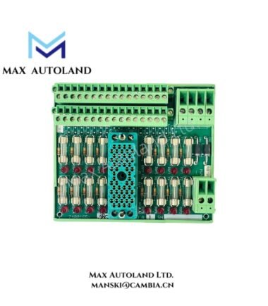
Overview
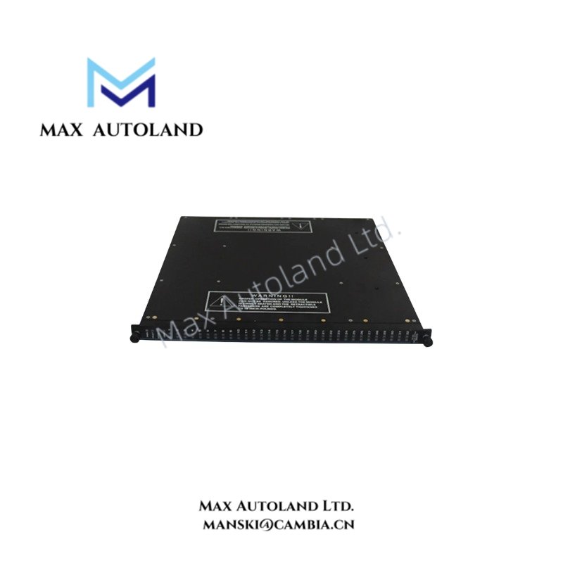
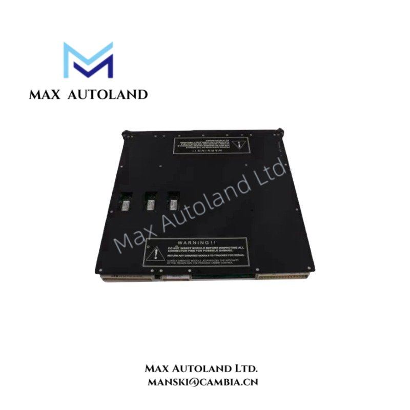
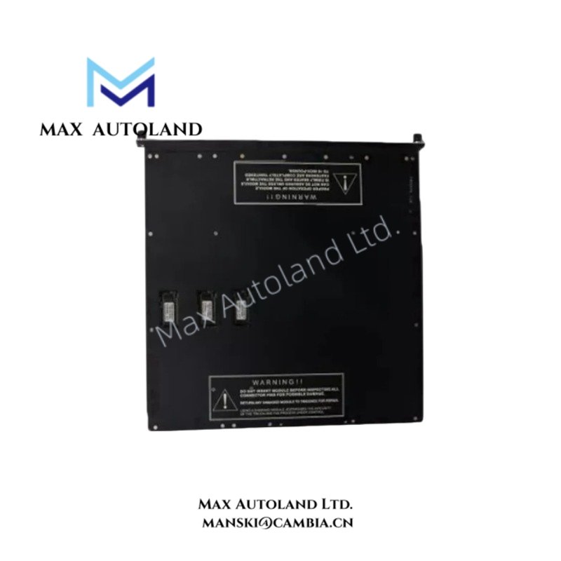
The Triconex 3505E, also cataloged as the 3505E TMR Digital Input Module, actively operates as a dedicated hardware component for monitoring 24 VDC digital field signals via triple modular redundancy architecture within Triconex safety instrumented systems.
Hardware Specifications
| Parameter | Specification |
|---|---|
| Model | 3505E |
| Brand | Triconex (Schneider Electric) |
| Power Consumption | 0.5 Watts per ON point (up to 1.5 Watts at max field voltage) |
| Number of Input Points | 32 points, commoned in groups of 8 |
| Nominal Input Voltage | 24 VDC |
| Operational Voltage Range | 20 to 42.5 VDC |
| Switching Threshold (OFF to ON) | > 12 VDC |
| Switching Threshold (ON to OFF) | < 4 VDC |
| Nominal Input Impedance | > 1.25 kOhm |
| Turn-On Current | 3 mA to 5 mA |
| Input Signal Delay (OFF to ON) | < 8 ms |
| Input Signal Delay (ON to OFF) | < 15 ms |
| Point Isolation | 1,500 VDC |
| Color Identification | Dark Red (Module Handle) |
Fail-Safe State Execution and Triple Modular Redundancy
Configured around a triple modular redundancy (TMR) 2oo3 architecture, the Triconex 3505E consistently guarantees uninterrupted process operations, even when an internal fault manifests within one of the system legs. Furthermore, this module enforces rigorous fail-safe state execution, making it an optimal deployment vector for Emergency Shutdown Systems (ESD) and Fire and Gas (F&G) protection loops. Galvanic isolation across input points actively ensures that high transient voltages do not propagate to adjacent system backplanes, thereby maintaining systemic integrity across safety instrumented systems.
Frequently Asked Questions
Q: Does the Triconex 3505E module support live insertion and removal under power?
A: Yes, the module supports online replacement within an active Triconex safety system chassis, provided technicians observe standard plant hot-swap procedures.
Q: How does the system group the input points for power distribution and isolation?
A: Engineers common the 32 input points in groups of 8, which permits structured isolation boundaries across field wiring segments.
Field Installation Guidelines
- Verify that the physical chassis slot matches the module configuration before insertion.
- Align the module carefully with the backplane connectors and apply firm, even pressure to engage the dark red handle locking mechanism.
- Ensure all field input wiring originating from field devices is properly terminated to the corresponding terminal blocks and shielded to reduce electromagnetic interference.
- Inspect nominal voltage levels to confirm they remain strictly within the 20 to 42.5 VDC operational window prior to system energization.
Triconex Top Products
| Triconex | Triconex | Triconex |
| 3625 | CM3201 | 4211 |
| 3700A | 7400207-001 | 9662-810 |
| 4329 | 7400209B-030 | 9563-810 |
| 3008 | 7400208C-020 | 9753-110 |
| 4119A | 7400209-030 | 9853-610 |
| 3636T | 8306A | 9761-210 |
| 3805E | 3625C1 | 4351B |
| 4351A | 3481 S2 | 3721 |
| DO3401 | 4210 | 8312 |
| DI3301 | 8111 | 3503E |
| 3664 | 9562 3000520-390 | MP3101 |


Reviews
There are no reviews yet.