



Overview
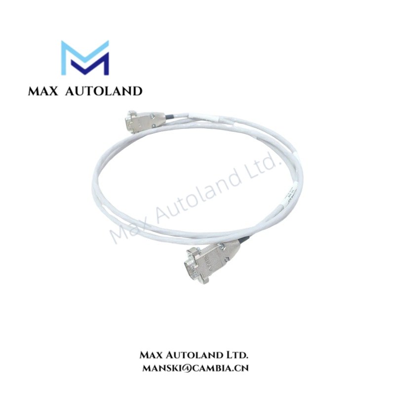
The Invensys 4000103-520, also cataloged as the 4000103-520 Ethernet interface cable, operates as a dedicated hardware component for 10/100 Mbit/s Tricon data link execution within Tricon safety instrumented system architectures.
Hardware Specifications
| Parameter | Specification |
|---|---|
| Model | 4000103-520 |
| Brand | Invensys |
| Origin | Standard Industrial Manufacturing |
| Weight | 0.8 kg (Estimated) |
| Dimensions | Nominal 20 ft / 6.1 m length |
| Operating Temp | -40 to 85 deg C |
| Power Consumption | Low-level data service passive transmission |
| Voltage Rating | 300 V |
| Current Rating | Low-level data service |
| Characteristic Impedance | 100 Ohm +/- 15% |
| Electrical Isolation | 1,500 V DC conductor-to-shield |
Triple Modular Redundancy (TMR) 2oo3 Architecture Integration
Because this cable assembly is deployed within the Tricon safety instrumented system, signal integrity directly impacts the triple modular redundancy (TMR) 2oo3 architecture. The 4 x 24 AWG conductor configuration combined with an overall shielded data construction prevents electromagnetic interference (EMI) from corrupting safety-critical communication loops. Furthermore, the 1,500 V DC conductor-to-shield electrical isolation protects the communication channels from ground loops and common-mode transients, thereby ensuring that the fail-safe state execution remains uncompromised during transient fault conditions.
Frequently Asked Questions
Q: What are the routing limitations when deploying this cable in an industrial enclosure?
A: You must maintain a safe physical separation between high-voltage power conduits and this data cable to prevent induced noise. Avoid exceeding the minimum bend radius recommended for industrial multi-pair shielded cables.
Q: Does this cable support hot-swapping of system modules?
A: While physical communication cables can be disconnected during maintenance windows, doing so on active safety loops will trigger channel fault diagnostics and may invoke safety controller redundancy degradation alarms depending on system configuration.
Field Installation Guidelines
- Verify that the physical nameplate, hardware revision, and connector layout match your project configuration sheets before beginning installation.
- Ensure both connector ends are fully seated and securely latched to the respective chassis or baseplate ports to prevent intermittent communication drops.
- Ground the overall shielding construction correctly at the designated panel termination points to maintain continuous electromagnetic shielding performance.
- Protect the industrial flame-retardant jacket from sharp metal edges, excessive pulling tension, and high-vibration stress zones during routing.
Triconex Top Products
| Triconex | Triconex | Triconex |
| 3625 | CM3201 | 4211 |
| 3700A | 7400207-001 | 9662-810 |
| 4329 | 7400209B-030 | 9563-810 |
| 3008 | 7400208C-020 | 9753-110 |
| 4119A | 7400209-030 | 9853-610 |
| 3636T | 8306A | 9761-210 |
| 3805E | 3625C1 | 4351B |
| 4351A | 3481 S2 | 3721 |
| DO3401 | 4210 | 8312 |
| DI3301 | 8111 | 3503E |
| 3664 | 9562 3000520-390 | MP3101 |


Reviews
There are no reviews yet.