
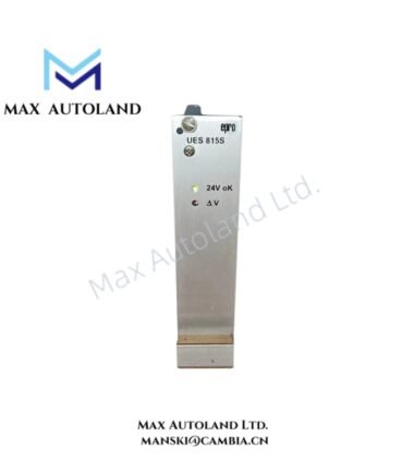
Overview
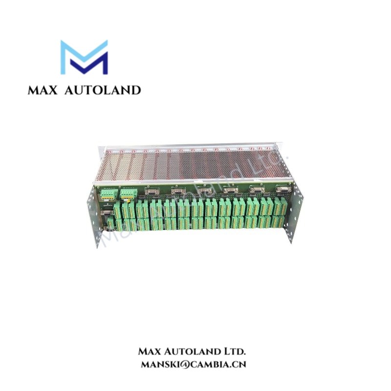
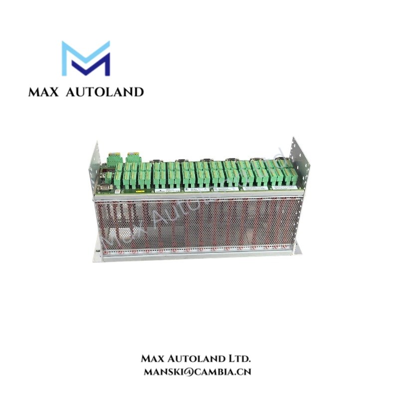
Configured for physical card mounting, power distribution, and signal interconnection in the AMS 6500 ATG system, the Emerson EPRO A6500-SR (A6500-SR System Rack) provides the rack-level mechanical and electrical interface for protection, relay, and communication cards. The 19-inch chassis uses an 84HP, 3RU format and provides plug-in spring terminals and D-Sub interfaces for field and sensor signal connections.
Hardware Specifications
| Parameter | Specification |
|---|---|
| Model | A6500-SR |
| Brand | Emerson EPRO |
| Series | AMS 6500 ATG |
| Product Type | System Rack / Enclosure Chassis |
| Weight | Approx. 2,400 g |
| Dimensions | 19-inch rack, 84HP width, 3RU height |
| Operating Temp | -20 deg C to +70 deg C with forced cooling; up to +55 deg C without forced cooling |
| Storage Temp | -40 deg C to +85 deg C |
| Relative Humidity | 5 to 95%, non-condensing |
| Nominal Supply Voltage | +24 VDC redundant |
| Supply Voltage Range | +19 to +32 VDC |
| Power Consumption | Slots: <100 W; outputs: <150 W |
| Protection Class | IP20 when rack-mounted |
| Protection Card Capacity | Up to 11 protection/measuring cards |
| Relay Card Capacity | 1 relay card |
| Communication Card Capacity | Up to 2 communication cards |
| Protection Card Width | 6HP per A6500-UM / A6500-TP position |
| Relay Card Width | 10HP for A6500-RC |
| Communication Card Width | 4HP per A6500-CC position |
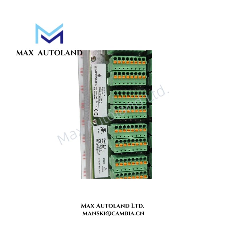
| Power / I/O Terminals | Pluggable push-in spring cage connections |
| Power Wiring Capacity | Up to 2.5 mm2 |
| I/O Wiring Capacity | Up to 1.5 mm2 |
| Raw Signal Interface | Shielded D-Sub 9 connectors |
| D-Sub Locking | UNC 4-40 screw locks |
| Hazardous Area Approvals | ATEX / IECEx / CSA |
| Hazardous Area Classification | Class I Div 2, Zone 2 / Ex nA nC IIC T4 Gc |
| Standard Form Factor | IEC 60297 compatible 19-inch rack format |
AMS 6500 ATG Backplane and Signal Interface
The A6500-SR provides the physical backplane for installed protection, relay, and communication cards. The rack routes card power and I/O connections through pluggable spring cage terminals, while shielded D-Sub 9 connectors provide the raw sensor signal interface.
The rack accepts up to 11 protection or measuring cards, one relay card, and two communication cards. The specified card widths and rack width establish the 84HP mechanical allocation. The communication card positions can support a redundant communication-card arrangement when the installed system configuration requires it.
The rack uses redundant +24 VDC supply inputs. The specified operating supply range is +19 to +32 VDC. Wiring uses removable push-in spring cage terminals, which provide direct termination without separate screw-terminal blocks.
Frequently Asked Questions
Q: What card capacity does the A6500-SR provide?
A: The rack provides positions for up to 11 protection or measuring cards, one relay card, and two communication cards within the 84HP rack width.
Q: What interfaces connect sensor and field wiring to the rack?
A: The rack uses pluggable push-in spring cage terminals for power and I/O wiring. Shielded D-Sub 9 connectors provide the raw sensor signal interface.
Q: What supply voltage does the A6500-SR require?
A: The specified nominal supply is redundant +24 VDC, with an operating range of +19 to +32 VDC.
Field Installation Guidelines
Install the A6500-SR in a compatible 19-inch mounting structure and maintain the required mechanical clearance for card insertion and wiring access.
Verify the rack position and card allocation before installing protection, relay, or communication modules. Do not exceed the stated card positions or mechanical width allocation.
Connect the redundant DC supply through the designated rack terminals. Verify supply polarity and voltage before energizing the rack.
Route raw sensor wiring separately from high-current power conductors where practical. Use shielded wiring for the D-Sub sensor interfaces and terminate shields according to the system grounding design.
Secure D-Sub connectors using the specified UNC 4-40 locking hardware. Ensure each spring cage terminal is fully engaged and that conductor sizes remain within the stated terminal capacity.
Where the installation uses hazardous-area approvals, verify that the complete installed assembly, field wiring, connected modules, and enclosure configuration satisfy the applicable ATEX, IECEx, or CSA installation requirements.


Reviews
There are no reviews yet.