

Overview
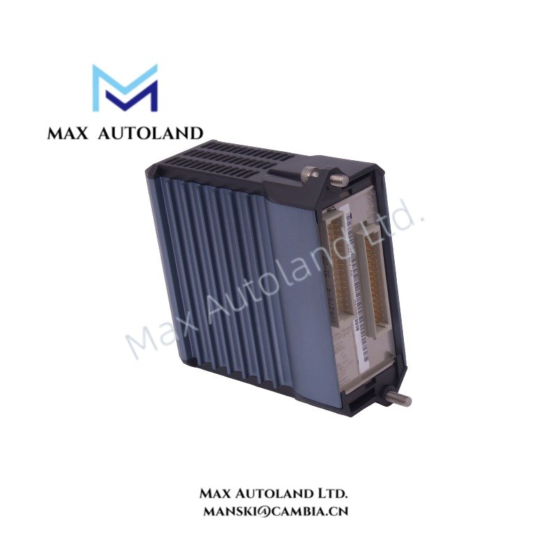
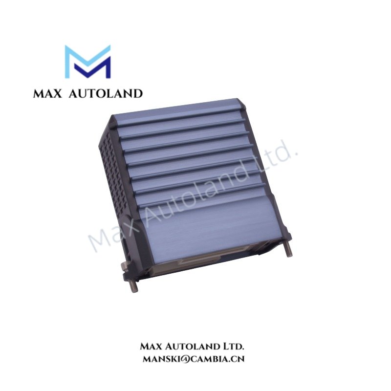
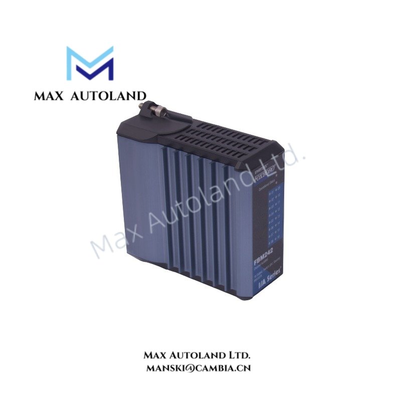
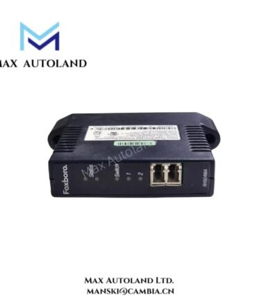
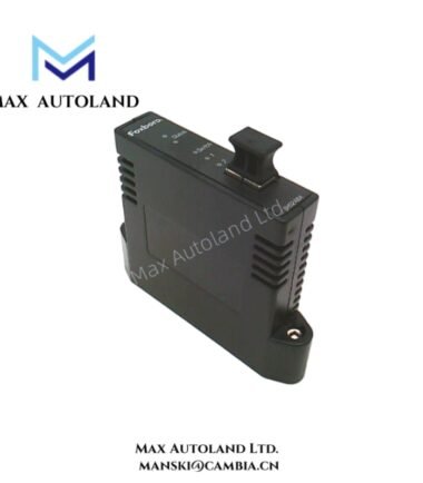
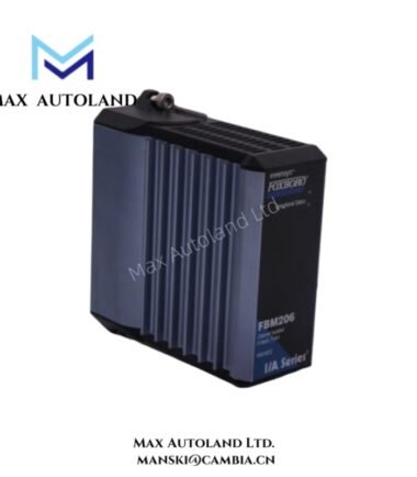
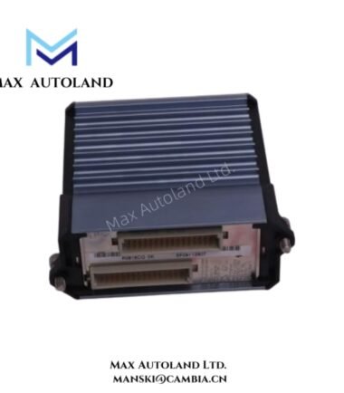
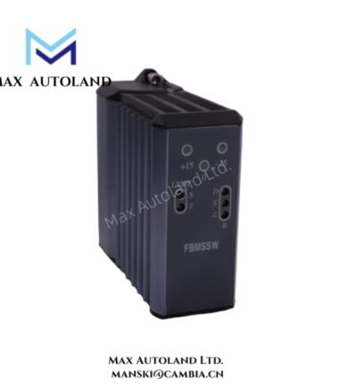
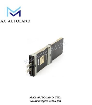
The Foxboro P0971HX, also cataloged as the FBM242 Externally Sourced Discrete Output Interface Module, operates as a dedicated hardware component for discrete signal execution within the Foxboro I/A Series / EcoStruxure Foxboro DCS Module Fieldbus network.
Hardware Specifications
| Parameter | Specification |
|---|---|
| Model | P0971HX / FBM242 |
| Brand | Foxboro |
| Origin | USA |
| Product Type | Digital Output Modules |
| Weight | Approx. 284 g |
| Dimensions | 102 mm H x 45 mm W x 104 mm D; 114 mm H including mounting lugs |
| Operating Temp | -20 deg C to +70 deg C |
| Power Consumption | Maximum 3 W at 24 VDC |
| Channel Count | 16 independent discrete output channels |
| Output Type | Externally sourced isolated discrete outputs |
| Output Voltage Range | 15 to 60 VDC maximum |
| Load Current | Up to 2.25 A per channel |
| In-Rush Current | 8.0 A maximum for 20 ms at 30 deg C; 6.4 A maximum for 20 ms at 70 deg C |
| On-State Voltage Drop | 0.2 V maximum at 2.25 A |
| Off-State Leakage Current | 0.1 mA maximum |
| Isolation Method | Galvanic isolation between channels and ground |
| Communication Interface | Redundant 2 Mbps Module Fieldbus connection to FCM or FCP |
| Input Power Supply | 24 VDC (+5%, -10%) redundant supply |
| Maximum Heat Dissipation | 6.5 W at full output load condition |
| Storage Temperature | -40 deg C to +70 deg C |
| Relative Humidity | 5% to 95%, non-condensing |
| Altitude Range | -300 m to +12,000 m |
| Environmental Classification | ISA S71.04 Class G3 harsh environment compatibility |
| Housing Material | Extruded aluminum |
| Indicator Interface | Front panel operational status and channel activity LEDs |
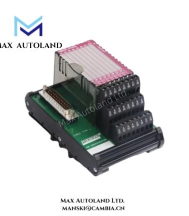
| Supported Termination Assemblies | Direct output, relay output, fused or current-limited field termination options |
DCS Process Interface and Channel Isolation
The Foxboro FBM242 uses isolated output channels to control external field loads without sharing electrical paths between channels. Therefore, each output maintains galvanic separation from adjacent channels and earth ground, reducing interference from industrial electrical noise.
Moreover, the externally sourced architecture allows field devices to receive power from an independent supply circuit. This design supports direct switching applications for relays, solenoids, indicators, and motor contactor interfaces while keeping module power loading separated from field energy requirements.
The module communicates with the Foxboro control architecture through the redundant 2 Mbps Module Fieldbus. In addition, the FBM242 supports Termination Assemblies that adapt field connections for different voltage levels, including relay conversion applications up to higher AC or DC switching requirements.
For Foxboro DCS installations, the module design aligns with process control requirements such as channel-to-channel isolation and signal conditioning for discrete field execution. Furthermore, the isolated architecture supports stable operation when multiple field circuits operate simultaneously in electrically noisy environments.
Frequently Asked Questions
Q: Does the Foxboro FBM242 supply field power directly to connected loads?
A: No. The FBM242 uses an externally sourced output design. Field devices receive operating power from an external supply connected through the selected Termination Assembly.
Q: How does the FBM242 protect output channels from electrical interference?
A: Each output channel provides galvanic isolation from other channels and ground, which limits unwanted electrical coupling and improves signal separation.
Q: Can the FBM242 support different field output voltage configurations?
A: Yes. The module supports 15 to 60 VDC direct outputs, while compatible Termination Assemblies provide relay-based interfaces for higher AC or DC switching applications.
Field Installation Guidelines
- Install the FBM242 inside the designated Foxboro I/A Series or EcoStruxure Foxboro DCS field control hardware enclosure.
- Verify that the redundant 24 VDC module power supply meets the specified voltage tolerance before energizing the module.
- Connect field wiring through the approved Termination Assembly to maintain correct isolation and protection characteristics.
- Separate discrete output wiring from high-voltage power cables to reduce electromagnetic interference.
- Use proper shield grounding practices when field wiring requires additional noise suppression.
- Confirm output polarity, external supply connection, and load current requirements before commissioning.
- Inspect front panel LED indicators after installation to verify module operating status and channel activity.



Reviews
There are no reviews yet.