
Overview
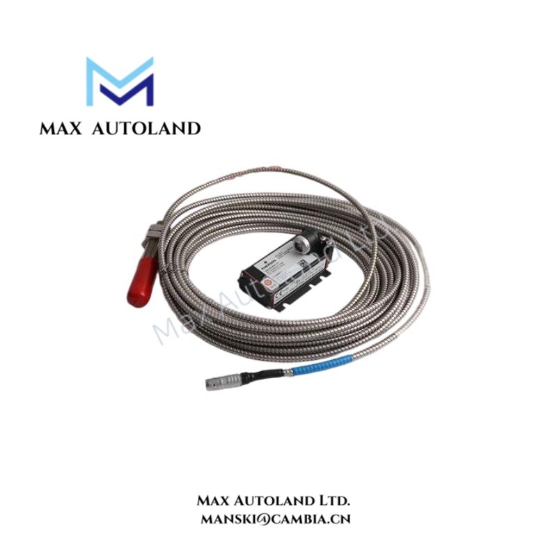
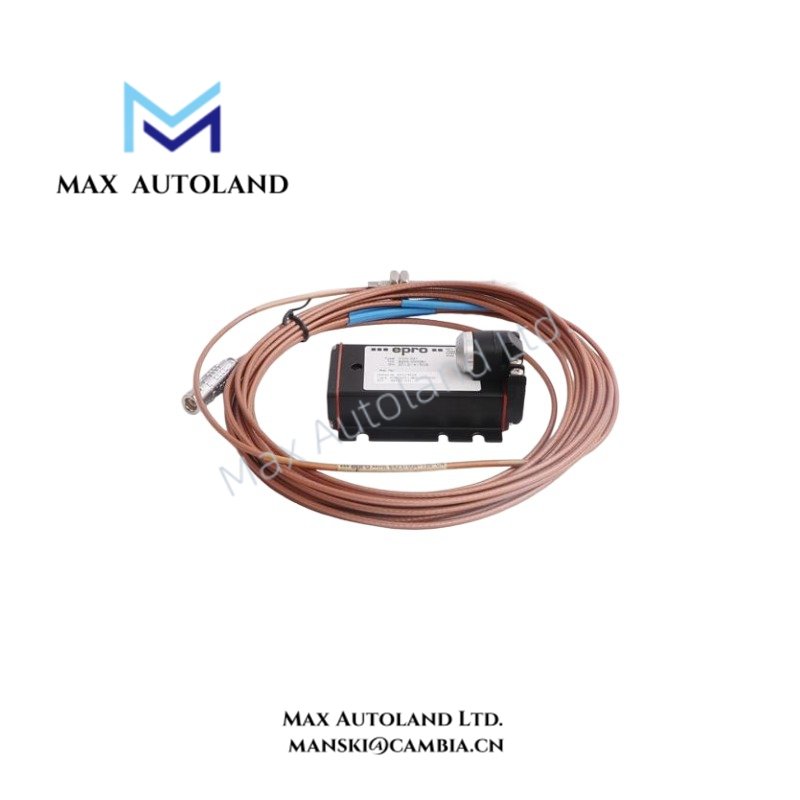
The Epro PR6424/003-030, also cataloged as the PR6424 16 mm Eddy Current Displacement Sensor, measures non-contact shaft displacement and vibration through electromagnetic induction. The probe converts changes in the electrical field between its sensing tip and a conductive target into displacement signals for compatible machinery monitoring systems.
Hardware Specifications
| Parameter | Specification |
|---|---|
| Model | PR6424/003-030 |
| Brand | Epro (Emerson) |
| Product Type | 16 mm Eddy Current Displacement Sensor |
| Series | PR6424 |
| Sensor Principle | Non-contact eddy current measurement |
| Probe Tip Diameter | 16 mm |
| Linear Measurement Range | Static: +/- 2.0 mm |
| Dynamic Measurement Range | 0 to 1,000 um |
| Sensitivity | 4 V/mm (101.6 mV/mil) |
| Linearity | +/- 1.5% |
| Nominal Center Air Gap | Approximately 2.7 mm |
| Frequency Response | 0 Hz to 20 kHz, system dependent |
| Target Material | Ferromagnetic steel |
| Factory Calibration Material | Standard 42CrMo4 steel |
| Minimum Shaft Diameter | 80 mm |
| Operating Temp | -35 to +150 deg C |
| Sensor Head Pressure Resistance | Up to 10,000 hPa |
| Housing Material | Stainless steel sleeve |
| Cable Material | PTFE |
| Cable Configuration | Configuration-dependent protective armor options |
| Certifications | CE; API 670 compliance stated in supplied specifications |
| Hazardous Area Options | ATEX, IECEx, and CSA variants available depending on system configuration |
Eddy Current Measurement and Signal Characteristics
The PR6424/003-030 uses electromagnetic coupling between the probe coil and the conductive shaft surface. As the shaft moves relative to the probe tip, the coupling changes and produces a corresponding electrical output through compatible driver electronics.
The 16 mm sensing geometry supports displacement measurement on large rotating shafts. The specified linear range is +/- 2.0 mm under the stated calibration conditions.
For machinery monitoring applications, the measurement system can provide shaft displacement information for radial vibration, axial movement, rotor position, and eccentricity analysis.
The probe’s stated frequency response extends from 0 Hz to 20 kHz, subject to the connected measurement system.
Frequently Asked Questions (FAQ)
Q: Can the PR6424/003-030 measure both static displacement and dynamic shaft vibration?
A: Yes. The supplied specifications identify a static measurement range of +/- 2.0 mm and a dynamic range of 0 to 1,000 um. Actual system performance depends on the compatible driver and monitoring electronics.
Q: Does the PR6424/003-030 operate independently without a signal conditioner?
A: The probe operates as part of an eddy current measurement system. Compatible driver electronics are required to excite the probe and process its measurement signal.
Q: Does the /003-030 suffix define the complete cable and mounting configuration?
A: The supplied information does not provide a verified suffix breakdown. Confirm the probe drawing, cable arrangement, connector type, and mounting dimensions against the applicable manufacturer documentation before installation.
Field Installation Guidelines
- Verify the probe model and mechanical dimensions against the equipment installation drawing.
- Confirm that the target shaft material matches the specified calibration material or the applicable system calibration requirements.
- Position the probe perpendicular to the target surface for radial displacement measurement.
- Establish the nominal operating gap according to the compatible driver documentation.
- Secure the probe sleeve using the specified mounting hardware and prevent mechanical movement during operation.
- Route the sensor cable separately from high-current power conductors and switching circuits where practical.
- Avoid sharp cable bends, excessive tensile loading, and contact with hot or moving machinery components.
- Apply cable shielding and grounding according to the monitoring system manufacturer’s instructions.
- Verify the signal output and measurement response before placing the machinery protection system into service.
- Confirm the installed configuration against the equipment drawings and applicable machinery monitoring requirements.


Reviews
There are no reviews yet.