

Overview
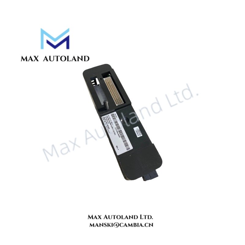
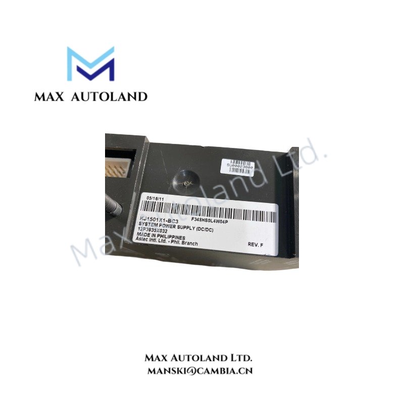
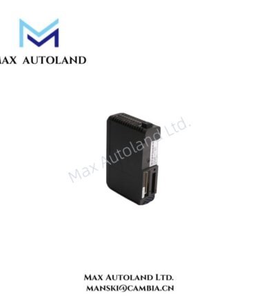
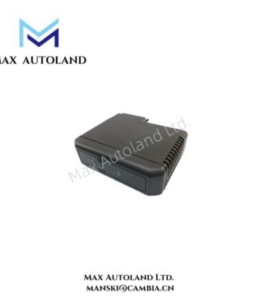
Configured for regulated DC power conversion in the DeltaV system power network, the Emerson KJ1501X1-BC3 (VE5009 Enhanced DC/DC System Power Supply Module) provides direct voltage conversion and auxiliary power execution for DeltaV controllers, I/O interfaces, and LocalBus components.
Hardware Specifications
| Parameter | Specification |
|---|---|
| Model | VE5009 |
| Brand | Emerson |
| Origin | USA |
| Product Type | Enhanced DC/DC System Power Supply Modules |
| Part Number | KJ1501X1-BC3 |
| Alternate Part Numbers | 12P3935X032, 12P3935X022 |
| System Platform | DeltaV Distributed Control System |
| Input Voltage | 12 VDC or 24 VDC bulk DC input |
| Input Current | 24 VDC @ 6.1 A nominal; 12 VDC @ 14.8 A nominal |
| Output Voltage | 12 VDC LocalBus output; 5.1 VDC and 3.4 VDC auxiliary outputs |
| Output Current | 12 VDC @ 8 A with 24 VDC input; 12 VDC @ 13 A with 12 VDC input |
| Auxiliary Power Output | 5.1 VDC @ 2.0 A and 3.4 VDC @ 2.0 A; total auxiliary power 10.2 W |
| Power Consumption | Based on input loading and connected DeltaV system load |
| Weight | Approximately 0.5 kg to 0.6 kg |
| Dimensions | Approximately 4.4 cm x 17.8 cm x 11.4 cm |
| Operating Temp | -40 deg C to +60 deg C without derating; +60 deg C to +70 deg C with derating |
| Storage Temp | -40 deg C to +70 deg C |
| Relative Humidity | 5% to 95%, non-condensing |
| Mounting Type | T-type DIN rail mounting on DeltaV Power/Controller Carrier |
| Hold-up Time | Output remains within 5% of nominal for >= 5 ms at full load |
| Protection | Output overvoltage protection at 110% to 120%; internal non-replaceable fuse |
| Environmental Rating | ISA-S71.04-1985 Class G3 airborne contaminants |
| Vibration Resistance | 1 mm p-p at 5-16 Hz; 0.5 g at 16-150 Hz |
| Shock Resistance | 10 g half-sine wave for 11 ms |
DCS Power Conversion and Signal Interface Characteristics
The VE5009 module converts plant DC supply input into regulated voltage rails for DeltaV controller and I/O assemblies. It supports both 12 VDC and 24 VDC input configurations, while the internal conversion stage maintains LocalBus voltage output for connected system components.
Furthermore, the module supports redundant power arrangements through load-sharing operation. Multiple power supply modules can distribute system load, allowing the DeltaV power architecture to maintain operation during individual module faults.
The Emerson DeltaV power architecture focuses on controlled DC distribution rather than field signal processing. Therefore, the module does not provide 4-20 mA HART loop handling, FOUNDATION Fieldbus communication, or Profibus PA interface functions. These functions remain assigned to dedicated DeltaV I/O modules and field interface components.
The module design also supports channel-to-channel electrical separation within the wider DeltaV system architecture. This separation reduces interference between controller power distribution and field signal processing sections.
Frequently Asked Questions
Q: Can the VE5009 operate with both 12 VDC and 24 VDC input sources?
A: Yes. The VE5009 accepts either 12 VDC or 24 VDC bulk DC input and provides regulated outputs according to the selected input configuration.
Q: Does the VE5009 support redundant power configurations?
A: Yes. The module supports load-sharing operation with multiple power supplies installed in redundant DeltaV power architectures.
Q: Does the VE5009 provide field signal conditioning functions?
A: No. The VE5009 provides DC power conversion and auxiliary voltage output. Field signal conditioning functions require dedicated DeltaV I/O modules.
Field Installation Guidelines
Install the VE5009 on the specified DeltaV Power/Controller Carrier using the T-type DIN rail mounting interface. Verify that the bulk DC supply wiring matches the configured 12 VDC or 24 VDC input requirements before energizing the module.
Route DC power conductors separately from high-voltage switching cables and high-current motor wiring to reduce electrical interference. Maintain proper grounding practices for the DeltaV cabinet structure and connect protective earth according to site electrical standards.
Before commissioning, inspect the module seating position, carrier connections, and power distribution terminals. For redundant configurations, confirm correct load-sharing connections between installed power supply modules before applying system power.



Reviews
There are no reviews yet.