
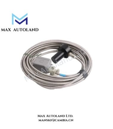
Overview
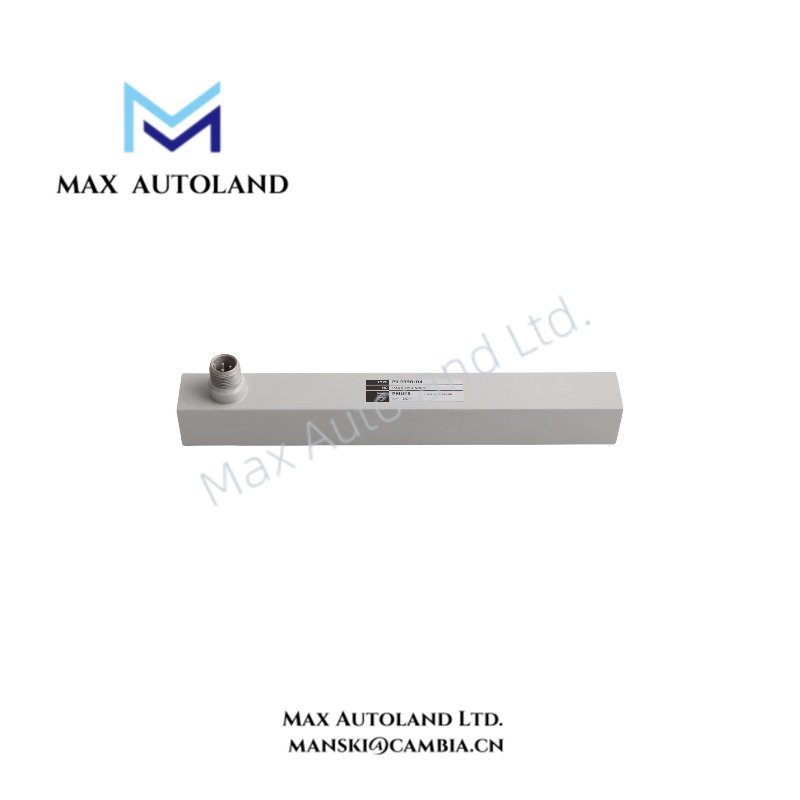
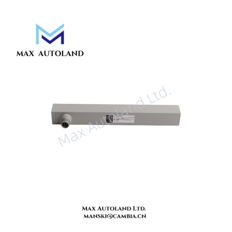
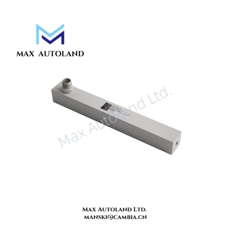
Configured for linear displacement measurement in the PR9350 sensor system, the Emerson EPRO PR9350/04 (PR9350 inductive sensor) converts tracing-pin movement into a bridge voltage proportional to displacement. The sensor uses a ferromagnetic core, differential windings, and carrier-frequency excitation. Emerson documents the PR9350 series for static and dynamic displacement measurement and specifies compatibility with the A6500-LC LVDT Converter and A6500-UM Universal Measurement Card. (Emerson.com)
Hardware Specifications
| Parameter | Specification |
|---|---|
| Model | PR9350/04 |
| Brand | Emerson / EPRO |
| Series | PR9350 |
| Product Type | Inductive displacement sensor |
| Measurement Principle | Differential inductive measurement with ferromagnetic tracing pin |
| Measuring Range | -50 mm to 0 to +50 mm |
| Sensitivity | 270 mV/V |
| Linearity Error | +/- 2.5% at 100% of measuring range |
| Linearity Error at 60% Range | +/- 0.5% |
| Operating Temp | -35 deg C to +120 deg C for specified temperature influence |
| Temperature Influence | < 3% |
| Sensor Supply Voltage | 5 Vrms |
| Sensor Supply Current | 27 to 50 mA |
| Carrier Frequency | 3 to 5 kHz |
| Capacitance | 250 pF per winding |
| Dynamic Measurement | Up to 1250 Hz |
| Dimensions | A: 197 mm; B: 229 mm; C: 112 mm; D: 150 mm; E: 144.1 mm; F: 25.4 mm |
| Mounting Thread | M4 internal fixing holes |
| Tracing Pin Thread | M3 |
| Electrical Connector | 3-pole Cannon connector |
| Origin | Germany |
The current Emerson installation guide confirms the PR9350/04 measuring range, sensitivity, supply requirements, dimensional data, and electrical characteristics. (Emerson.com)
Emerson EPRO Inductive Measurement Characteristics
The PR9350/04 uses two differential windings around a movable ferromagnetic core. As the tracing pin moves from the center position, the winding impedances change in opposite directions. A carrier-frequency Wheatstone bridge then produces an output voltage proportional to the mechanical displacement. (Emerson.com)
The PR9350/04 provides a nominal measuring range of -50 mm to +50 mm and a sensitivity of 270 mV/V. Emerson specifies a linearity error of +/- 2.5% at full measuring range and +/- 0.5% at 60% of the measuring range. (Emerson.com)
For system integration, the sensor uses 5 Vrms excitation at a carrier frequency of 3 to 5 kHz. The documented supply current is 27 to 50 mA. The sensor can perform dynamic measurements up to 1250 Hz. (Emerson.com)
The sensor has a 3-pole Cannon connector and an M3 threaded tracing pin. The housing provides internal M4 fixing threads for mechanical installation. (Emerson.com)
Frequently Asked Questions
Q: What excitation does the PR9350/04 require?
A: The sensor requires 5 Vrms excitation with a carrier frequency of 3 to 5 kHz. The specified sensor supply current is 27 to 50 mA. (Emerson.com)
Q: How does the PR9350/04 generate its displacement signal?
A: A ferromagnetic core moves within differential windings. The resulting impedance change is converted through a carrier-frequency Wheatstone bridge into a voltage proportional to tracing-pin displacement. (Emerson.com)
Q: What mechanical connections are provided?
A: The sensor provides internal M4 fixing threads for mounting and an M3 thread at the tracing-pin end for connection to the measuring target. (Emerson.com)
Field Installation Guidelines
Mount the sensor using the specified M4 fixing points and mechanically connect the tracing pin to the measuring target through its M3 threaded end. Maintain the sensor alignment with the actual displacement axis to prevent measurement errors. (Emerson.com)
Use the specified 5 Vrms sensor excitation and connect the sensor according to the applicable connector pin assignment. Emerson states that incorrect polarity or improper installation can produce signals that do not represent the measured quantity. (Emerson.com)
Route the sensor wiring separately from high-power switching conductors where practical. Maintain appropriate shielding and grounding practices for low-level measurement circuits. The sensor is shielded for radio-interference immunity, but Emerson notes that interference can occur when peripheral equipment is inadequately shielded. (Emerson.com)
Before commissioning, verify the mechanical position, electrical connections, and sensor excitation. For maintenance checks, Emerson provides coil-resistance reference values for the PR9350/04. Between A and C, the documented range is approximately 46.0 ohm to 54.0 ohm; between A and B or B and C, it is approximately 23.0 ohm to 27.0 ohm. (Emerson.com)


Reviews
There are no reviews yet.