
Overview
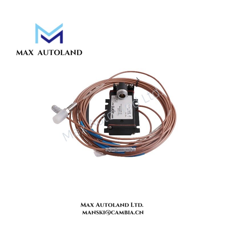
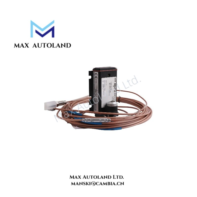
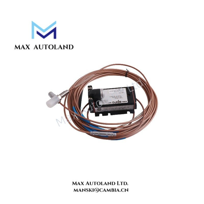
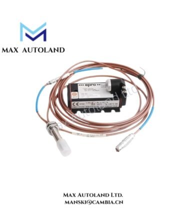
The Emerson EPRO PR6423/10R-030-CN, also cataloged as the PR6423/10R-030 eddy current proximity sensor, converts electromagnetic field variations into proportional voltage signals for non-contact shaft displacement and vibration measurement. It provides an 8 mm sensing interface for machinery monitoring applications involving radial vibration, axial displacement, shaft position, and eccentricity.
Hardware Specifications
| Parameter | Specification |
|---|---|
| Model | PR6423/10R-030-CN |
| Base Model | PR6423/10R-030 |
| Brand | Emerson / EPRO |
| Product Type | Eddy Current Proximity Sensor |
| Origin | Not specified |
| Weight | 0.32 kg |
| Dimensions | 18 x 17 x 4 cm (estimated shipping dimensions) |
| Sensor Tip Diameter | 8 mm |
| Measurement Range | 2 mm |
| Sensitivity | 8 V/mm (203.2 mV/mil), +/- 5% |
| Frequency Range | 0 to 20 kHz (-3 dB) |
| Target Material | Ferromagnetic steel |
| Calibration Material | AISI/SAE 4140 / 42CrMo4 |
| Minimum Shaft Diameter | 25 mm |
| Operating Temp | -35 to +180 deg C, including integrated cable |
| Sensor Tip Material | PEEK |
| Housing Material | Stainless steel |
| Protection Rating | IP66 |
| Compatible Converters | EPRO CON011, CON021, CON031, CON041 |
| System Compatibility | EPRO/Emerson MMS machinery protection systems |
Eddy Current Measurement and Signal Conditioning
The PR6423/10R-030-CN uses electromagnetic induction to detect changes in the distance between the probe tip and a conductive shaft target. As the shaft moves, the probe generates a corresponding electrical signal through its compatible signal conditioning circuit.
The sensor supports the following measurement functions:
- Radial shaft vibration monitoring.
- Axial displacement and thrust position measurement.
- Static shaft position measurement.
- Shaft eccentricity monitoring.
- Dynamic displacement measurement within the specified frequency range.
For accurate measurements, the installation must account for target material, probe clearance, mounting geometry, and converter compatibility.
The stated sensitivity of 8 V/mm applies to the specified measurement configuration. Verify the complete probe and converter combination before commissioning.
Process Instrumentation and Signal Interface
The PR6423/10R-030-CN operates as a sensing element within an EPRO/Emerson eddy current measurement chain. Its electrical output requires compatible signal conditioning before integration into machinery monitoring equipment.
The system configuration should address:
- Probe and converter model compatibility.
- Cable and connector configuration.
- Sensor-to-target clearance.
- Target material and surface condition.
- Signal polarity and measurement scaling.
- Electrical shielding and grounding.
Unlike a conventional 4-20 mA process transmitter, this probe belongs to an eddy current displacement measurement system. Therefore, do not assume direct 4-20 mA HART connectivity or interchangeability with standard process transmitters.
Frequently Asked Questions (FAQ)
Q: What physical parameter does the PR6423/10R-030-CN measure?
A: It measures the relative displacement between the probe tip and a conductive target. The resulting signal supports shaft vibration, axial position, radial displacement, and eccentricity monitoring.
Q: Can the PR6423/10R-030-CN connect directly to a PLC analog input?
A: The probe requires compatible signal conditioning. Verify the converter output type and electrical interface before connecting it to a PLC or machinery monitoring input.
Q: Does the sensor support high-temperature operation?
A: The specified operating temperature range is -35 to +180 deg C, including the integrated cable. Confirm the complete assembly’s temperature limits and installation conditions before deployment.
Field Installation Guidelines
- Verify the complete model designation and confirm compatibility with the selected EPRO signal converter.
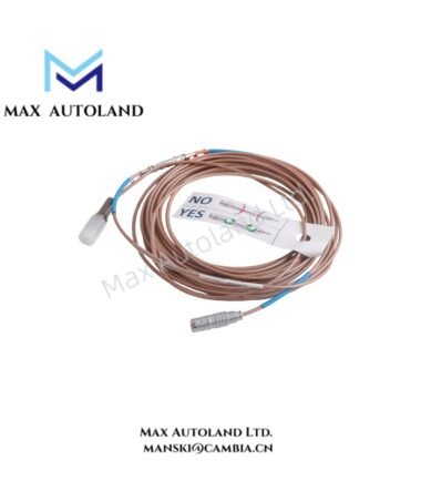
- Inspect the probe tip, integrated cable, connector, and mounting threads for physical damage.
- Install the probe perpendicular to the target surface where required by the measurement geometry.
- Confirm that the target material matches the specified ferromagnetic calibration material.
- Establish the probe clearance according to the applicable converter documentation and measurement requirements.
- Route probe cables separately from high-voltage power conductors and sources of electromagnetic interference.
- Maintain cable shielding and grounding according to the equipment manufacturer’s installation instructions.
- Check signal polarity, output scaling, and measurement response before enabling machinery protection functions.
- Verify the installed probe’s mechanical clearance throughout the expected shaft movement range.


Reviews
There are no reviews yet.