
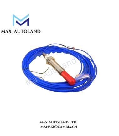
Overview
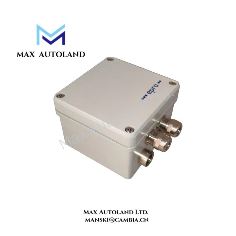
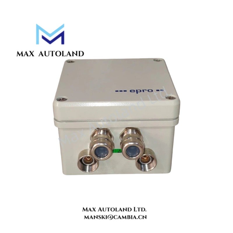
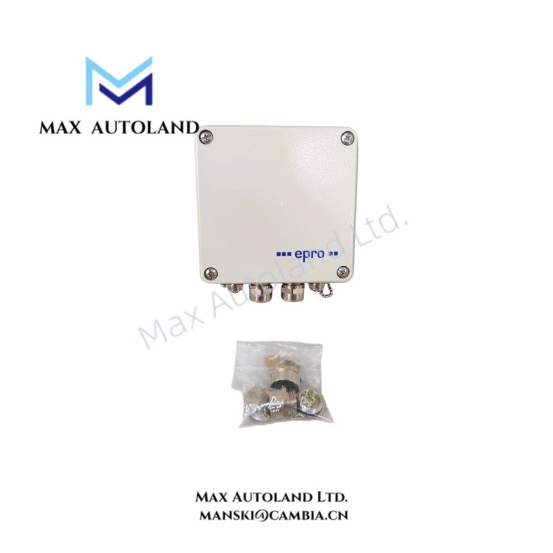
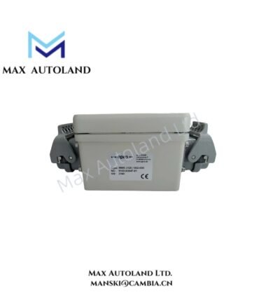
Configured for dual-channel relative shaft vibration measurement in the EPRO MMS 3000 system, the Emerson EPRO MMS3110/011-000 (MMS3110 Dual-Channel Shaft Vibration Transmitter) processes signals from two eddy-current sensor channels. The specified configuration uses internal signal converters, RS-232 communication, two characteristic-value outputs, and five function outputs without an integrated display. (PROFESS)
Hardware Specifications
| Parameter | Specification |
|---|---|
| Model | MMS3110/011-000 |
| Brand | Emerson EPRO |
| Series | MMS 3000 |
| Product Type | Dual-Channel Shaft Vibration Transmitter |
| Origin | Germany |
| Sensor Inputs | 2 independent eddy-current sensor inputs |
| Compatible Sensors | EPRO PR 6422, PR 6423, PR 6424, PR 6425 series |
| Signal Conversion | Internal signal converters |
| Communication Interface | RS-232 |
| Bus Communication | Not provided in the standard /011-000 configuration |
| Characteristic-Value Outputs | 2 outputs, system-referenced |
| Function Outputs | 5 optocoupler outputs in the standard configuration |
| Display | None in the standard configuration |
| Current Output | 0/4 to 20 mA or 20 to 4/0 mA, depending on configured output direction |
| Maximum Current-Output Burden | 500 Ohm |
| Output Protection | Open-circuit and short-circuit proof |
| PR 6422 Measuring Range | 0 to 250 um o-p |
| PR 6423 Measuring Range | 0 to 500 um o-p |
| PR 6424 Measuring Range | 0 to 1000 um o-p |
| PR 6425 Measuring Range | 0 to 1000 um o-p |
| High-Pass Filter | 1 / 5 / 10 Hz |
| Low-Pass Filter | 50 to 1500 Hz |
The MMS3110/011-000 documentation identifies the unit as a standard MMS 3110 configuration with internal converters, RS-232, system-referenced characteristic-value outputs, five function outputs, and no display. The sensor input range depends on the connected PR 642x sensor type. (PLC DCS Pro Ltd.)
Machinery Signal Processing
The transmitter accepts two independent signals from compatible EPRO eddy-current sensors. Each channel processes the sensor signal for shaft-vibration measurement before transmitting the selected characteristic value through the analog output interface. The documented sensor combinations include PR 6422, PR 6423, PR 6424, and PR 6425, with different measurement ranges. (PLC DCS Pro Ltd.)
The frequency response can be configured with high-pass filter settings of 1, 5, or 10 Hz and a low-pass range from 50 to 1500 Hz. Therefore, the filter configuration determines the dynamic signal band presented to the measurement function. (PLC DCS Pro Ltd.)
For the standard /011-000 configuration, RS-232 provides the communication interface. In addition, two system-referenced characteristic-value outputs and five optocoupler function outputs are provided. Other MMS 3110 order configurations can use different communication, output, and display options; these alternatives should not be assumed for MMS3110/011-000. (PROFESS)
Frequently Asked Questions
Q: Which sensors can be connected to the MMS3110/011-000?
A: The documented sensor inputs support EPRO PR 6422, PR 6423, PR 6424, and PR 6425 eddy-current sensor series. The applicable measurement range depends on the selected sensor. (PLC DCS Pro Ltd.)
Q: What communication interface is specified for MMS3110/011-000?
A: The standard /011-000 configuration uses RS-232 and does not include bus communication. RS-485 and PROFIBUS DP are listed as alternative MMS 3110 configuration options, not as standard functions of this order code. (PROFESS)
Q: Does MMS3110/011-000 include function outputs?
A: Yes. The documented /011-000 configuration provides five function outputs using optocouplers. A relay or PhotoMos configuration belongs to other MMS 3110 ordering options. (PROFESS)
Field Installation Guidelines
- Verify the transmitter order code before installation because MMS 3110 communication and output configurations vary by suffix.
- Connect only compatible EPRO PR 642x sensor types and verify the required measurement range before commissioning.
- Route sensor wiring separately from high-current power and switching conductors to reduce induced electrical interference.
- Maintain the sensor cable shield and grounding arrangement according to the installed EPRO system wiring documentation.
- Verify the RS-232 connection before applying configuration parameters.
- Confirm the analog output range and polarity before connecting the output to a PLC, DCS, or protection system.
- Check the function-output wiring against the configured optocoupler interface before connecting external trip or alarm circuits.
- Confirm the high-pass and low-pass filter settings during commissioning so that the selected bandwidth matches the required shaft-vibration measurement.
- Installation and commissioning should be performed by trained personnel. (PROFESS)


Reviews
There are no reviews yet.