
Overview
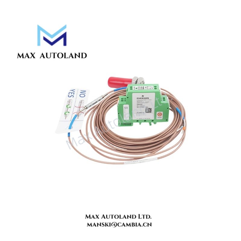
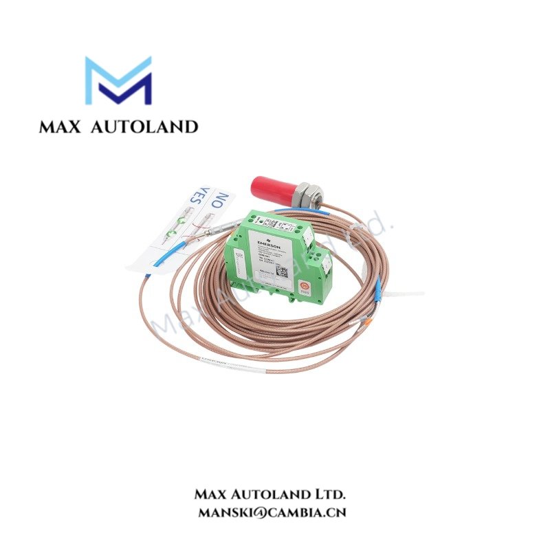
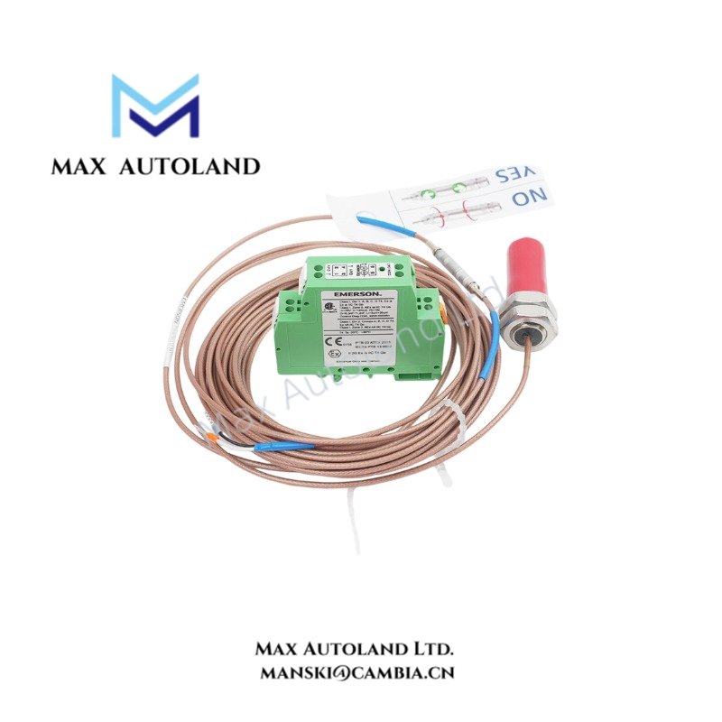
The Emerson EPRO CON041 + PR6423/009-031-CN, comprising the CON041 signal converter and PR6423/009-031-CN 8 mm proximity sensor, measures shaft displacement through electromagnetic eddy-current coupling. The converter processes probe signals and provides electrical outputs for machinery monitoring systems. The assembly supports static and dynamic displacement measurement when configured as a compatible measuring chain.
Hardware Specifications
| Parameter | Specification |
|---|---|
| Model | CON041 + PR6423/009-031-CN |
| Brand | Emerson EPRO |
| Product Type | Eddy Current Measurement Chain |
| Included Components | CON041 Signal Converter + PR6423/009-031-CN Sensor |
| Sensor Head Diameter | 8 mm |
| Sensor Thread | M10 x 1 (configuration-dependent; verify before installation) |
| Linear Measurement Range | 2 mm (80 mils) |
| Initial Air Gap | Typically 0.5 mm (20 mils); verify calibration |
| Sensitivity | Approximately 8 V/mm (203.2 mV/mil) |
| Sensor Operating Temperature | -35 to +180 deg C |
| Converter Operating Temperature | -30 to +100 deg C |
| Converter Frequency Range | 0 to 20,000 Hz (-3 dB) |
| Converter Housing Material | PA 6.6 Polyamide |
| Converter Protection Class | IP20 |
| Target Material | Electrically conductive ferromagnetic steel |
| Signal Processing | Static and dynamic displacement signal conversion |
Eddy Current Measurement and Signal Conversion
The PR6423/009-031-CN sensor generates an electromagnetic field near the conductive shaft surface. Changes in the probe-to-target distance modify the electromagnetic coupling and produce corresponding electrical signal variations.
The CON041 converter processes these variations to provide measurement outputs for monitoring equipment.
The measurement chain supports the following physical parameters, subject to system configuration:
- Radial and axial shaft displacement
- Shaft position and relative vibration
- Rotor eccentricity
- Differential expansion measurement when installed in a suitable measurement arrangement
The specified 2 mm linear range and approximately 8 V/mm sensitivity describe the supplied sensor information. Confirm the complete chain calibration before applying these values to protection-system calculations.
Converter Signal Characteristics and Measurement Compatibility
The CON041 operates with the associated eddy-current probe to convert displacement-dependent signals into electrical measurement outputs.
Its specified frequency response extends from DC to 20 kHz at the -3 dB points. Consequently, the converter supports both static position measurements and dynamic displacement signals within its configured operating range.
However, the supplied documentation does not specify output voltage limits, supply voltage, connector pin assignments, or detailed calibration tolerances. Verify these parameters against the applicable manufacturer documentation before connecting the assembly to a machinery protection system.
Frequently Asked Questions (FAQ)
Q: Can the CON041 + PR6423/009-031-CN measure both static and dynamic shaft displacement?
A: Yes. The measurement chain processes displacement-dependent signals for static and dynamic monitoring. Its specified converter frequency range is 0 to 20,000 Hz (-3 dB).
Q: What is the linear measurement range of the PR6423/009-031-CN sensor?
A: The supplied specification identifies a 2 mm (80 mils) linear measurement range. Maintain the required installation gap and verify the calibrated operating range before commissioning.
Q: Can the CON041 converter operate at the sensor’s maximum temperature?
A: No. The supplied specifications identify different temperature limits. The sensor range is -35 to +180 deg C, while the converter range is -30 to +100 deg C. Install each component within its respective temperature rating.
Field Installation Guidelines
- Verify component compatibility: Confirm that the CON041 converter matches the PR6423/009-031-CN sensor and its calibration requirements.
- Inspect the mounting location: Check the probe mounting arrangement, target surface condition, and available installation clearance.
- Establish the measurement gap: Set the initial probe-to-target distance according to the applicable calibration documentation.
- Route signal cables carefully: Separate sensor wiring from high-current power conductors and switching circuits where practical.
- Manage cable shielding: Apply the manufacturer’s grounding and shielding instructions to reduce electromagnetic interference and ground-loop effects.
- Protect the converter: Install the IP20-rated converter in an enclosure appropriate for the site’s environmental conditions.
- Verify operating temperatures: Keep the sensor and converter within their respective specified temperature ranges.
- Validate the measurement chain: Check signal polarity, output response, zero position, and calibration before connecting the assembly to machinery protection logic.


Reviews
There are no reviews yet.