



Overview
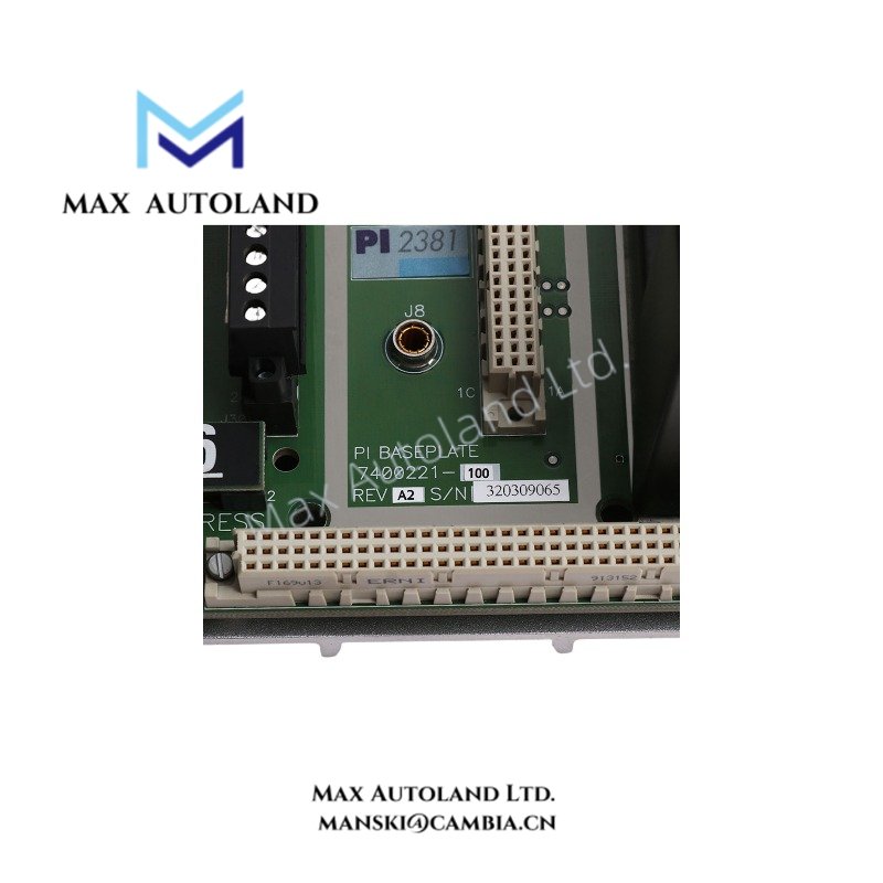
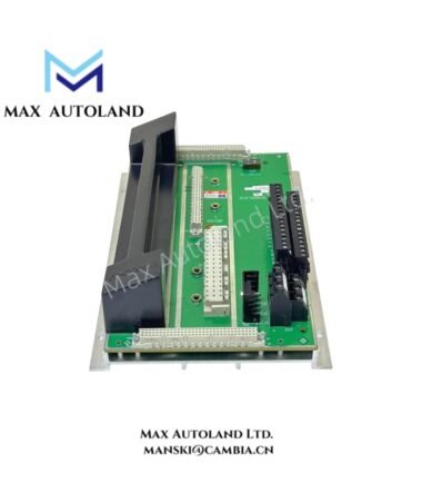
Configured for differential pulse signal termination in the Trident safety system, the Invensys 7400221-100 PI2381 (PI2381 pulse input baseplate) provides direct field termination for compatible pulse input channels. It supports magnetic, active, and open collector sensors through a six-channel differential input topology. The baseplate provides two redundant field power inputs, a configurable termination resistor, and a jumper-selectable pull-up resistor network.
Hardware Specifications
| Parameter | Specification |
|---|---|
| Model | 7400221-100 PI2381 |
| Brand | Invensys |
| Component Type | Pulse input baseplate |
| Assembly Number | 7400221-100 |
| Baseplate Model | PI2381 |
| Compatible Module | Trident PI3381 |
| Input Capacity | 6 pulse channels |
| Termination Method | Direct field termination |
| Supported Sensors | Magnetic, active, and open collector |
| Input Topology | Differential pulse wiring |
| Termination Resistor | Baseplate configurable |
| Pull-up Resistor | Jumper-selectable network |
| Field Power Inputs | Two redundant supplies |
| Fault Current | 130 mA typical |
| Maximum Fault Current | 200 mA |
| Unused Point Rule | Unused channels must be terminated |
| Installation Style | Panel-mounted Trident baseplate |
SIS Signal and Fail-Safe Interface Characteristics
The PI2381 baseplate terminates six differential pulse input channels for the Trident safety system. It accepts magnetic, active, and open collector sensor configurations. Therefore, field wiring must match the electrical characteristics of the connected sensor and the PI3381 pulse input module.
The baseplate provides two redundant field power inputs. This arrangement supports redundant power distribution to the connected field interface. However, the supplied data does not specify a transfer time or power-supply switching threshold.
The termination resistor can be configured at the baseplate, while the pull-up resistor network uses jumper selection. Consequently, technicians must verify the installed jumper configuration against the sensor interface before commissioning.
The specified fault current is 130 mA typical, with a maximum fault current of 200 mA. These values should be considered when checking field protection and wiring conditions.
Frequently Asked Questions
Q: How many pulse input channels does the PI2381 support?
A: The 7400221-100 PI2381 provides 6 pulse channels.
Q: Which sensor types can connect to the PI2381?
A: The baseplate supports magnetic, active, and open collector sensors.
Q: What happens to unused input channels?
A: Unused channels must be terminated according to the supplied installation requirement.
Field Installation Guidelines
Mount the PI2381 as a panel-mounted Trident baseplate and verify its mechanical position before connecting field wiring.
Confirm the installed assembly number, baseplate model, and compatible PI3381 module before termination. Then verify the differential polarity and channel assignment for each pulse input.
Set the configurable termination resistor according to the connected sensor interface. Also, verify the jumper-selected pull-up resistor network before applying field power.
Route pulse signal wiring separately from high-voltage and high-current conductors where practical. Maintain the intended signal pair together to reduce unwanted electrical coupling.
Terminate unused channels as specified. Finally, inspect the two redundant field power connections, field protection, connector seating, and wiring identification before system commissioning.
Triconex Top Products
| Triconex | Triconex | Triconex |
| 3625 | CM3201 | 4211 |
| 3700A | 7400207-001 | 9662-810 |
| 4329 | 7400209B-030 | 9563-810 |
| 3008 | 7400208C-020 | 9753-110 |
| 4119A | 7400209-030 | 9853-610 |
| 3636T | 8306A | 9761-210 |
| 3805E | 3625C1 | 4351B |
| 4351A | 3481 S2 | 3721 |
| DO3401 | 4210 | 8312 |
| DI3301 | 8111 | 3503E |
| 3664 | 9562 3000520-390 | MP3101 |


Reviews
There are no reviews yet.