
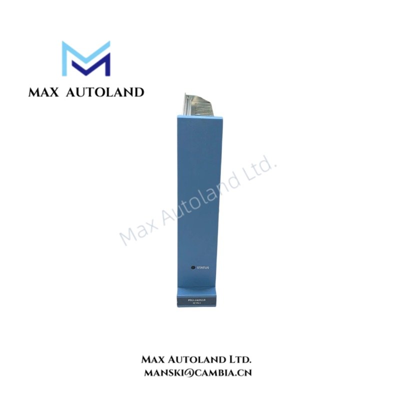
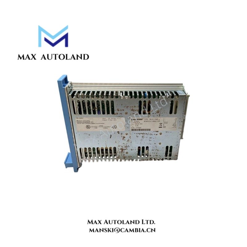
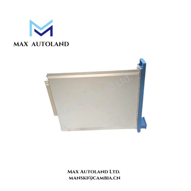
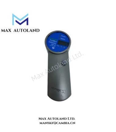
Overview
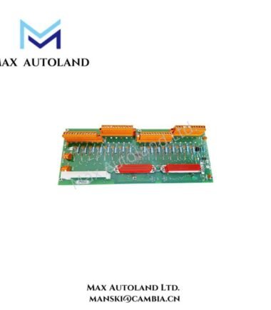
The Honeywell FC-PSU-240516, also cataloged as the FC-PSU-240516 Power Supply Unit, operates as a dedicated hardware component for dual-voltage power conversion within distributed control systems. It accepts a nominal input voltage range of 24 VDC and supplies dual regulated 5 VDC output rails for control processors and redundant or non-redundant input/output loops.
Hardware Specifications
| Parameter | Specification |
|---|---|
| Model | FC-PSU-240516 |
| Brand | Honeywell |
| Origin | USA |
| Weight | 0.88 kg |
| Dimensions | 3.5 x 22.5 x 17.5 cm |
| Operating Temp | -5 deg C to +70 deg C |
| Storage Temp | -40 deg C to +85 deg C |
| Relative Humidity | 10 to 95% (non condensing) |
| Power Consumption / Input Current | < 6 A at 24 Vin (16 A load) / < 7 A at 20.4 Vin (16 A load) |
| Input Voltage Range | 24 VDC (-15% to +30%) |
| Inrush Current | < 5 A at 24 Vin |
| Output Capacity | 16 A maximum across 5 V rails |
| Approvals | CE, TUV, UL, CSA, FM |
| Tariff Code | 8537101190 |
Channel Isolation and Power Conditioning Architecture
The module implements robust channel-to-channel isolation architectures to mitigate common-mode electrical noise propagation across process control loops and signal conditioning circuits. Configured for integration within industrial control nodes, the unit provides stable power regulation supporting 4-20 mA HART loop power conditioning and internal processor logic feeds. The dual 5 VDC output configuration is independently monitored to isolate fault conditions between the primary control processor and associated input/output modules, minimizing single-point failure risks during continuous industrial operation.
Frequently Asked Questions
Q: What are the restrictions regarding hot-swap operations for the FC-PSU-240516?
A: Hot-swap procedures are permitted only when the chassis backplane power bus is designed for live insertion and redundant power supply pairing is active to maintain system voltage continuity during module extraction.
Q: How does the internal circuit manage inrush current during system cold starts?
A: Integrated soft-start current-limiting circuitry restricts inrush current to less than 5 A at 24 Vin, preventing upstream breaker trips on shared distribution rails.
Q: What is the maximum load distribution limit across the dual 5 V outputs?
A: The unit delivers a combined load capability of up to 16 A maximum, dynamically allocated between the control processor rail and the input/output channel circuits.
Field Installation Guidelines
- Mount the power supply unit vertically on standard industrial backplanes or DIN rails, maintaining a minimum clearance of 50 mm above and below the housing to facilitate convective heat dissipation within the operating temperature range of -5 deg C to +70 deg C.
- Terminate incoming 24 VDC supply lines using copper conductors with a cross-sectional area rated for continuous currents up to 7 A. Securely attach the chassis ground terminal to the system protective earth (PE) busbar to ensure electromagnetic compatibility.
- Verify that input DC voltage levels remain within the specified 24 VDC (-15% to +30%) window prior to energizing the main supply circuit to prevent low-voltage lockout or thermal stress.




Reviews
There are no reviews yet.