
Overview
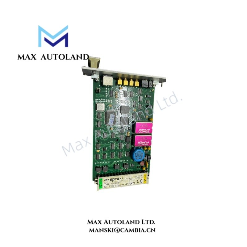
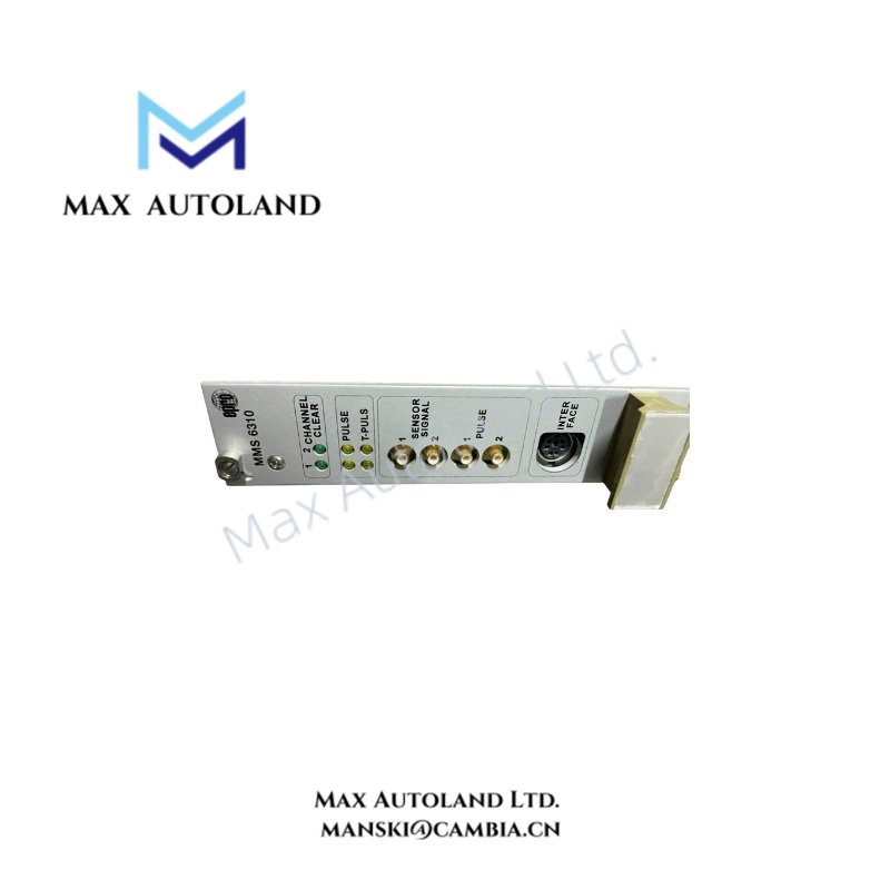
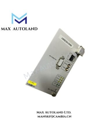
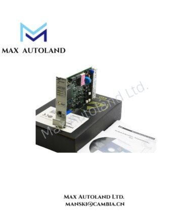
Configured for rotational speed measurement and overspeed protection, the EPRO MMS6350 (MMS 6350 Digital Overspeed Protection System) processes sensor frequency signals and provides speed-related output signals for machinery protection systems. It supports redundant +24 VDC power input and configurable monitoring outputs.
Hardware Specifications
| Parameter | Specification |
|---|---|
| Model | MMS6350 |
| Spare Model | MMS 6350 |
| Brand | EPRO |
| Manufacturer | EPRO |
| Product Type | Digital Overspeed Protection System / Speed Measurement Module |
| Weight | 0.2 kg |
| Dimensions | Estimated shipping size: 3.1 x 19 x 12.9 cm |
| Operating Temp | -40 deg C to +70 deg C |
| Input Type | Differential sensor inputs |
| Input Voltage Range | 0 to 30 VDC |
| Input Resistance | 100 kohm |
| Input Frequency Range | 0 Hz to 20 kHz |
| Maximum Measuring Speed | Up to 65,535 rpm, depending on trigger wheel tooth count |
| Current Outputs | 0/4 to 20 mA, 16-bit resolution |
| Dynamic / Pulse Outputs | TTL level, 0 to 5 V, up to 20 kHz |
| Binary Outputs | 6 configurable function/alarm outputs, maximum 48 VDC |
| Communication Interfaces | RS232, RS485; optional PROFIBUS-DP |
| Module Power Supply | Redundant +24 VDC inputs |
| Safety Application | Designed for SIL3-certified applications according to DIN EN 61508 |
| Module Format | Euro-format card, 100 x 160 mm |
| Connector Standard | DIN 41494 / DIN 41612 |
Overspeed Signal Processing
The MMS6350 receives differential sensor signals and processes the input frequency for rotational speed measurement. The specified input range extends from 0 Hz to 20 kHz, while the measurable speed can reach up to 65,535 rpm depending on trigger wheel tooth count.
The module provides 0/4 to 20 mA current outputs and TTL pulse outputs for transmission of speed-related signals. In addition, six configurable binary outputs support function and alarm signaling.
For system communication, the module provides RS232 and RS485 interfaces. A PROFIBUS-DP interface is also specified as an optional communication interface. The module accepts redundant +24 VDC power inputs for its power supply arrangement.
Frequently Asked Questions
Q: What type of sensor signal does the MMS6350 process?
A: The MMS6350 uses differential sensor inputs and accepts an input voltage range of 0 to 30 VDC. The specified input frequency range is 0 Hz to 20 kHz.
Q: What output signals are available from the MMS6350?
A: The module provides 0/4 to 20 mA current outputs, TTL pulse outputs from 0 to 5 V, and six configurable binary function/alarm outputs.
Q: Does the MMS6350 support redundant power input?
A: Yes. The supplied specifications identify redundant +24 VDC inputs for the module power supply.
Field Installation Guidelines
Install the MMS6350 in the specified Euro-format card system using the applicable DIN 41494 / DIN 41612 connector arrangement.
Route sensor signal wiring separately from high-voltage power conductors and high-current switching circuits. Use appropriate shielded signal cable where the installation requires protection against electrical interference.
Connect the sensor wiring according to the actual sensor interface and system wiring documentation. Verify signal polarity, voltage range, and frequency range before applying the input signal.
For current and pulse outputs, confirm that the receiving equipment matches the specified output type and electrical range. Keep signal wiring organized to reduce coupling from switching and power circuits.
Connect the redundant +24 VDC supply according to the system power distribution design. Verify the supply polarity and wiring before energizing the module.
Do not infer hot-swap capability, power consumption, or firmware compatibility without the applicable EPRO system documentation.


Reviews
There are no reviews yet.