
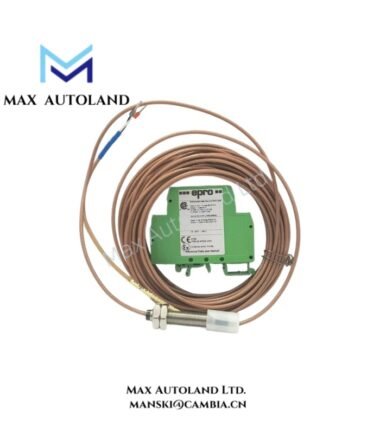
Overview
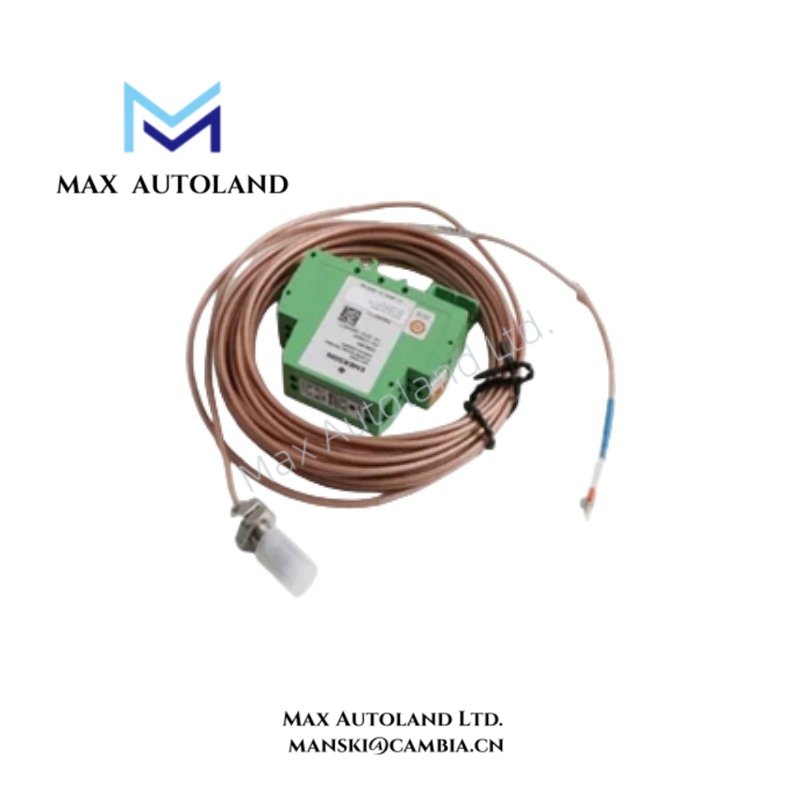
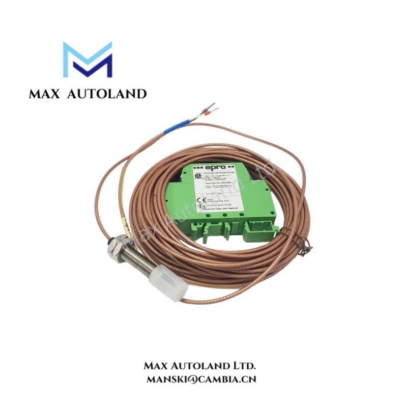
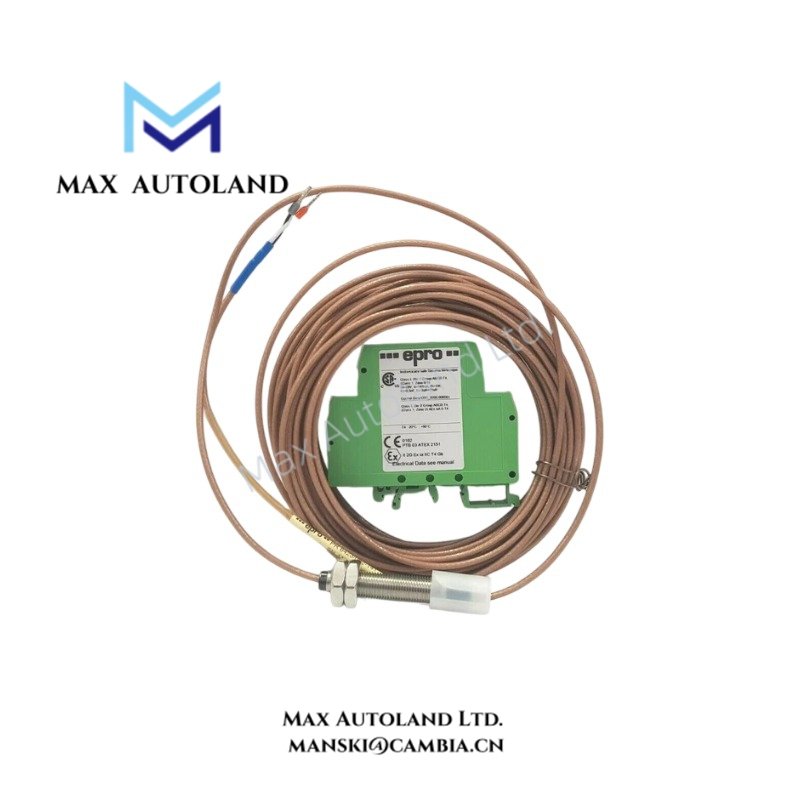
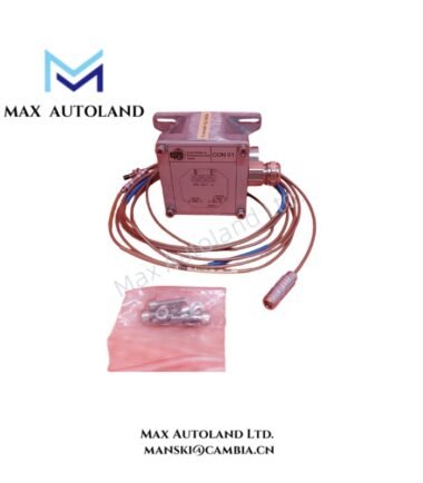
The Emerson EPRO CON010, cataloged as the CON010 eddy current signal converter, processes proximity probe signals for machinery monitoring systems. It converts sensor inputs into electrical signals for monitoring shaft vibration, axial displacement, and eccentricity. Exact electrical interfaces and operating limits require confirmation against the manufacturer documentation for the specific unit.
Hardware Specifications
| Parameter | Specification |
|---|---|
| Model | CON010 |
| Brand | Emerson EPRO |
| Product Type | Eddy Current Signal Converter |
| Compatible Probes | PR6423, PR6424, and PR6426 series |
| Frequency Range (-3 dB) | 0 Hz to 20,000 Hz |
| Power Supply | Reported as -23 VDC to -32 VDC |
| Operating Temp | Reported as -30 deg C to +100 deg C |
| Housing Material | Reported as aluminum alloy |
| Mounting | Screw mounting, as reported |
| Connections | Reported self-locking transducer plug and screw terminals; verification required |
Eddy Current Signal Processing and Interface Characteristics
Eddy current measurement depends on the interaction between the probe coil and the conductive target. The probe generates a distance-dependent electrical response, which the associated converter processes according to its configured measurement range and sensor characteristics.
For machinery monitoring, the probe and converter must use compatible calibration characteristics. Incorrect probe pairing or scaling can introduce errors in vibration amplitude and shaft displacement measurements. Verify the probe type, extension cable arrangement, measurement range, and output interface before integrating the converter with a monitoring or protection system.
The CON010-specific signal output range, calibration procedure, and interface characteristics have not been established by the supplied information. Do not assume compatibility with a particular 4-20 mA HART loop or fieldbus protocol without manufacturer documentation.
Frequently Asked Questions
Q: Which proximity probes can be used with the CON010?
A: The supplied information identifies the PR6423, PR6424, and PR6426 series. Confirm the exact probe and cable combination against the CON010 documentation before installation.
Q: What should be checked when validating the measurement signal?
A: Verify probe compatibility, cable connections, supply polarity, calibration range, and output scaling. Compare the measured response with the applicable manufacturer calibration data.
Q: Can the CON010 output connect directly to a PLC or DCS analog input?
A: Confirm the converter’s output type, voltage or current range, signal reference, and input loading requirements before connection. The available information does not establish a specific output range.
Field Installation Guidelines
- Verify the hardware: Check the model marking and confirm compatibility with the installed probe and monitoring equipment.
- Check the supply: Confirm the rated supply voltage and polarity from the manufacturer documentation before energizing the module.
- Connect the probe: Inspect the connector and cable for damage. Maintain the specified cable arrangement and avoid unapproved extensions.
- Separate signal wiring: Route probe and measurement wiring away from power conductors and other sources of electrical interference.
- Apply grounding practices: Follow the system grounding and cable-shield termination requirements. Avoid unintended ground loops.
- Validate the measurement: Check the zero position, calibration range, signal polarity, and output response against the approved commissioning procedure.
- Confirm system integration: Verify that the receiving monitor or controller accepts the converter’s actual output interface and scaling.


Reviews
There are no reviews yet.