
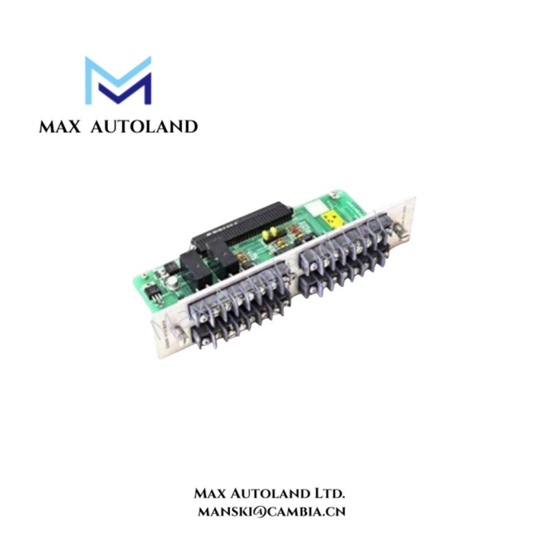
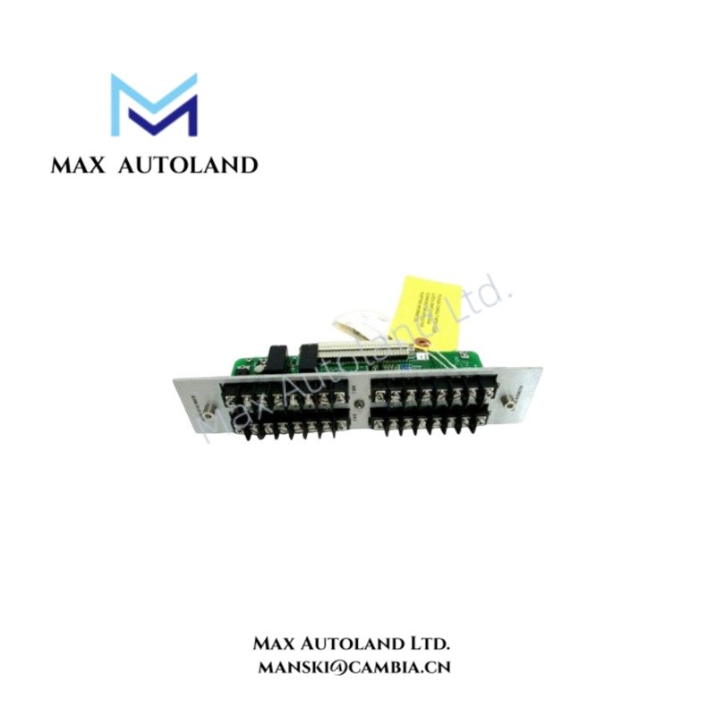
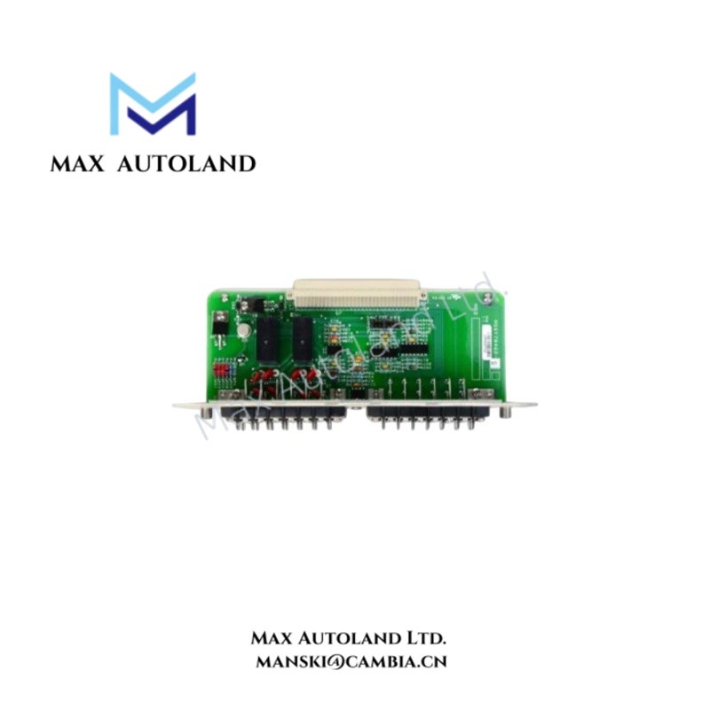
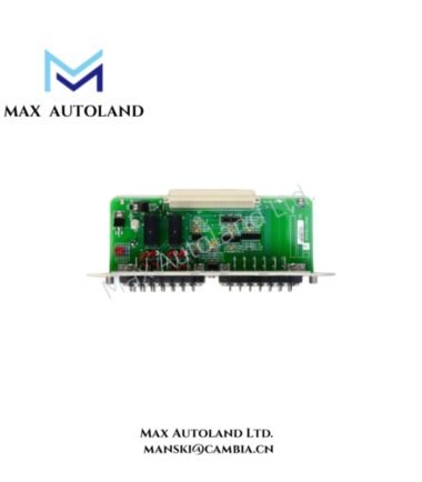
Overview
Hardware Specifications
| Parameter | Specification |
|---|---|
| Model | 82362-01 |
| Brand | Bently Nevada |
| Series | 3300 Series Monitoring System |
| Component Type | Printed Wiring Assembly (PWA) / System Monitor Module Board |
| Operating Input Voltage | 20 VDC to 34 VDC, system rack dependent |
| Probe Scaling Compatibility | 100 mV/mil (3.94 V/mm) or 200 mV/mil |
| Full Scale Range | Up to 2.0-0-2.0 mm, as specified |
| Analog Output | +4 mA to +20 mA proportional output support |
| Application | Machinery vibration, displacement, and condition-monitoring signal processing within compatible 3300 Series systems |
Eddy-Current Probe Scaling and Rotor Signal Processing
The supplied specifications identify compatibility with standard eddy-current proximity probe scaling of 100 mV/mil (3.94 V/mm) and 200 mV/mil. These scaling values define the relationship between probe output voltage and measured mechanical displacement.
For rotor monitoring, the probe signal represents changes in shaft position relative to the probe tip. Correct probe installation requires the probe gap and signal polarity to match the associated monitor channel configuration. The stated -10 VDC gap-voltage target is a general Bently Nevada eddy-current probe installation reference and should not be treated as a confirmed electrical specification of the 82362-01 assembly itself.
Frequently Asked Questions
Q: What supply voltage is identified for the 82362-01?
A: The supplied data specifies an operating input range of 20 VDC to 34 VDC, with the actual rack supply arrangement determining the applicable operating voltage.
Q: Does the 82362-01 support eddy-current probe signal scaling?
A: The supplied data identifies compatibility with 100 mV/mil (3.94 V/mm) and 200 mV/mil probe scaling configurations.
Q: Is the 82362-01 a standalone vibration sensor?
A: No. It is identified as a Printed Wiring Assembly used as internal hardware within compatible Bently Nevada 3300 Series monitoring equipment.
Field Installation Guidelines
- Verify the 82362-01 part number against the existing 3300 Series rack and monitor configuration before installation.
- Disconnect system power according to the equipment maintenance procedure before removing or installing the circuit assembly.
- Inspect the board connector and rack receptacle for contamination, damaged contacts, or mechanical deformation.
- Route probe and signal wiring separately from high-current switching conductors where practical.
- Maintain the specified probe polarity and signal wiring arrangement for the associated monitor channel.
- Use appropriate cable shielding and terminate shields according to the installed 3300 Series system wiring practice.
- Verify probe gap voltage and signal scaling at the associated monitor input before placing the channel into service.
- Confirm the analog output wiring and receiving-device input configuration before applying the channel to a control or recording system.






Reviews
There are no reviews yet.