
Overview
Hardware Specifications
| Parameter | Specification |
|---|---|
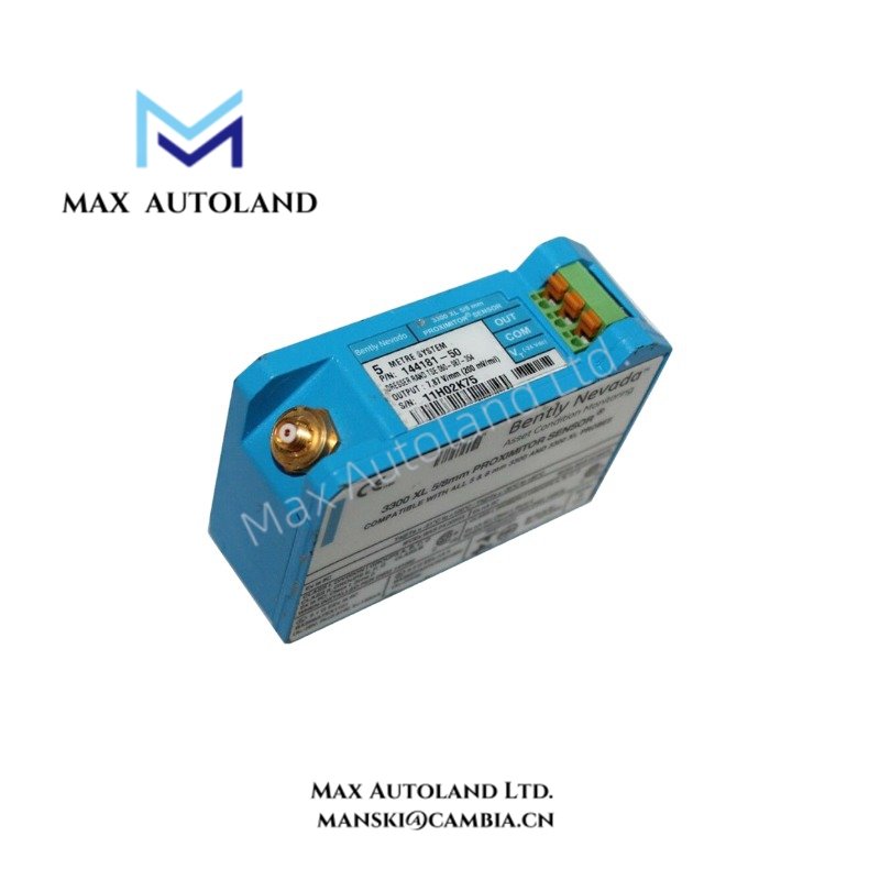
| Model | 144181-50 |
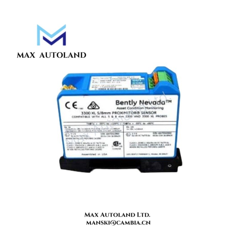
| Brand | Bently Nevada |
| Product Family | 3300 System |
| Component Type | Machinery Monitoring Component |
| Product Parameters | Machinery monitoring component |
| Channel Capacity | 2 channels |
| Input Type | Condition-monitoring transducer |
| Alarm Outputs | Alert and Danger levels |
| Buffered Output | Front-panel transducer signal |
| Status LEDs | OK, TX/RX, Bypass |
| Rack Space | One full-height slot |
| Backplane Supply | 3500/3300 rack power |
| Supply Voltage | -18 V DC to -26 V DC |
| Output Resistance | 50 W |
| Operating Temp | -35 deg C to +120 deg C |
| Storage Temp | -50 deg C to +120 deg C |
| Humidity | 0-100% RH, non-condensing |
| Exact Part Number | 144181-50 |
Machinery Monitoring Signal Characteristics
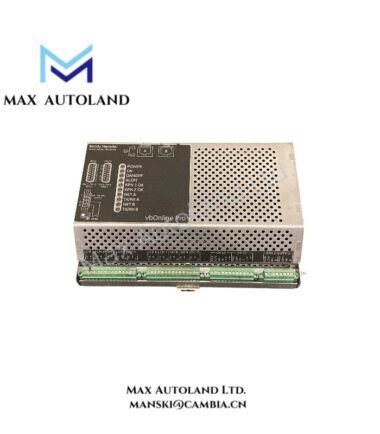
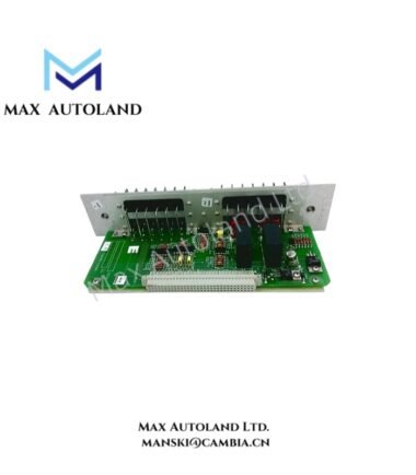
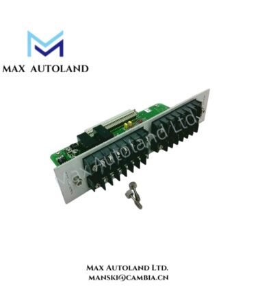
The 144181-50 accepts condition-monitoring transducer signals through its documented two-channel configuration. The monitoring path provides Alert and Danger alarm levels for machinery condition assessment. A front-panel buffered output provides access to the transducer signal for external measurement or diagnostic use.
For Bently Nevada machinery monitoring applications, signal integrity depends on correct transducer wiring, signal reference, shielding, and physical separation from high-current conductors. The supplied data does not specify an eddy-current probe scaling range, gap-voltage target, or cross-talk rejection value for this exact part number; these parameters should therefore be verified from the applicable system documentation before configuration.
Frequently Asked Questions
Q: How many monitoring channels are specified for the 144181-50?
A: The supplied specification identifies a two-channel configuration for condition-monitoring transducer signals.
Q: What alarm levels are provided?
A: The documented alarm outputs are Alert and Danger levels.
Q: Does the supplied data specify power consumption?
A: No. The available data specifies a supply voltage of -18 V DC to -26 V DC but does not provide a power-consumption value.
Field Installation Guidelines
Install the component in the specified full-height rack slot and verify mechanical seating before energizing the system. Confirm that the rack backplane and installed module configuration match the applicable 3300 System documentation.
Route transducer wiring separately from high-current and high-voltage conductors where practical. Maintain appropriate cable shielding and grounding practices for the installed monitoring system. Avoid unnecessary parallel routing with switching or power cables to reduce electrical interference.
Before commissioning, verify the supply voltage, transducer wiring polarity, channel assignment, alarm configuration, and buffered-output connections against the approved system drawings. Check the OK, TX/RX, and Bypass status indications after installation.
Do not infer power consumption, dimensions, weight, or additional environmental limits from related Bently Nevada modules. Use the applicable equipment manual and rack documentation for those values.





Reviews
There are no reviews yet.