
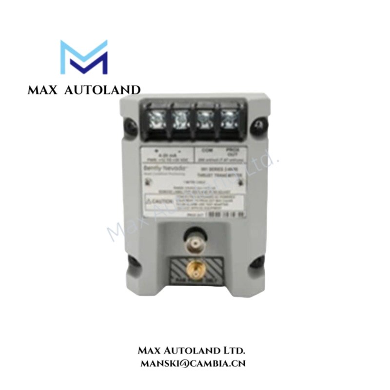
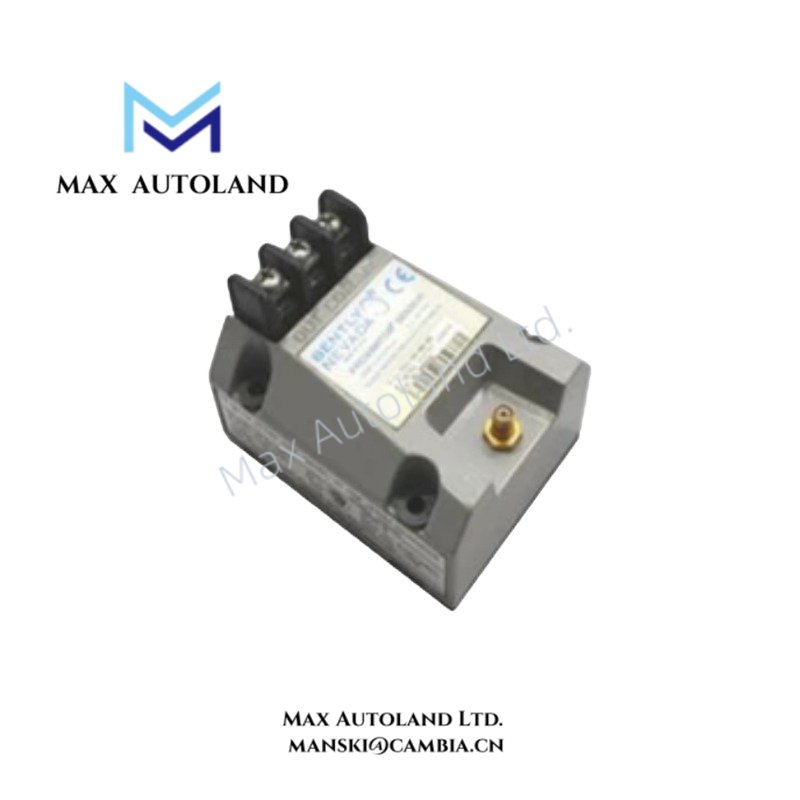
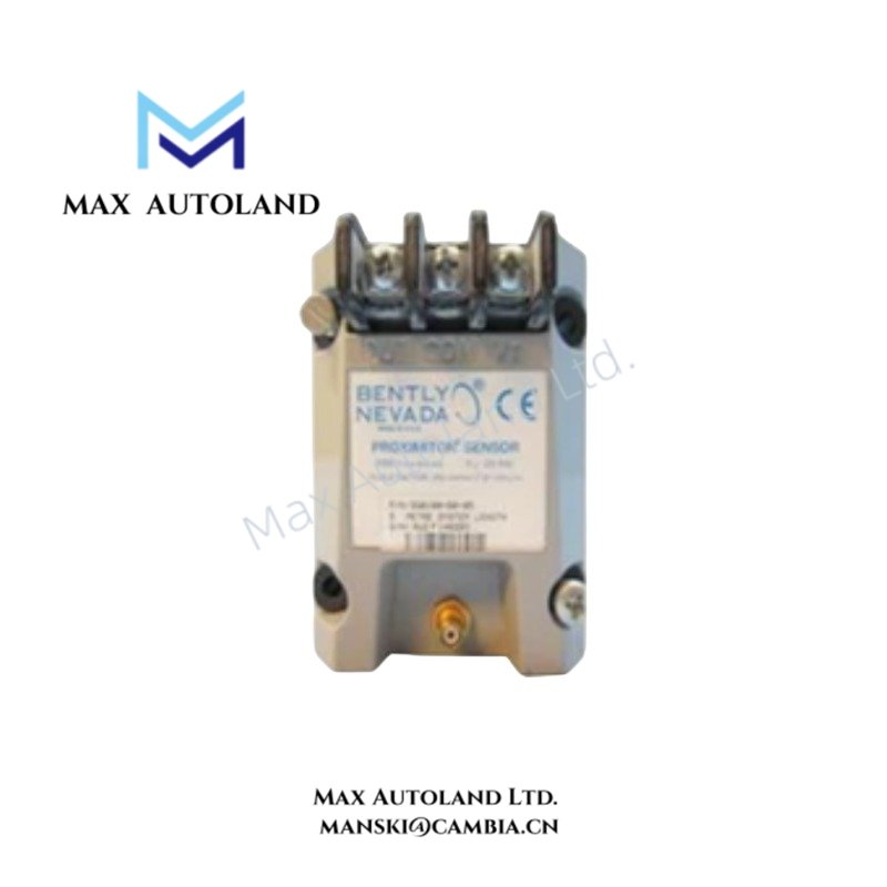
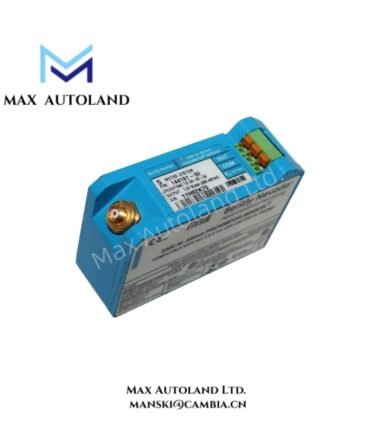
Overview
Hardware Specifications
| Parameter | Specification |
|---|---|
| Model | P3403893-0416 |
| Brand | Bently Nevada |
| Product Type | Vibration Transmitter |
| Measurement Type | Vibration |
| Input Configuration | Compatible vibration sensing input; exact sensor type not specified |
| Output Signal | 4-20 mA |
| Loop Configuration | Two-wire, loop-powered |
| Power Supply | 12 to 35 VDC |
| Dimensions | Approx. 7.5 cm x 6 cm x 10 cm |
| Weight | Approx. 0.55 kg |
| Installation Interface | Field wiring for two-wire analog loop |
| System Interface | PLC, DCS, or SCADA analog input |
Vibration Signal Scaling and Loop Interface
The P3403893-0416 converts a compatible vibration measurement into a 4-20 mA analog signal for transmission through a two-wire loop. The receiving analog input interprets loop current according to the configured measurement scaling.
Sensor compatibility must be verified before installation. If an eddy-current probe system is used, probe type, extension cable configuration, excitation requirements, and measurement scaling must match the transmitter input requirements. Gap voltage validation should follow the requirements of the connected sensing hardware.
The 4-20 mA circuit should use instrumentation wiring appropriate for the installation. Signal conductors should be routed separately from high-voltage and high-current switching circuits. Shield termination and grounding should follow the site instrumentation design to limit electromagnetic interference and ground-loop effects.
Frequently Asked Questions
Q: What output signal does the P3403893-0416 provide?
A: It provides a two-wire, loop-powered 4-20 mA analog output.
Q: What supply voltage is specified for the transmitter?
A: The supplied data specifies a 12 to 35 VDC supply range.
Q: Can the transmitter connect to a PLC or DCS analog input?
A: Yes. The 4-20 mA output can interface with a compatible analog input channel. The input must support the required loop configuration and electrical characteristics.
Field Installation Guidelines
- Verify the P3403893-0416 model and terminal configuration before wiring.
- Confirm that the connected vibration sensor matches the transmitter input requirements.
- Verify sensor scaling before commissioning the analog loop.
- Route vibration signal wiring separately from high-voltage power and high-current switching conductors.
- Use shielded instrumentation cable where required by the installation design.
- Terminate the cable shield according to the designated site grounding scheme.
- Verify loop polarity before applying 12 to 35 VDC.
- Confirm that the receiving PLC, DCS, or SCADA channel is configured for a 4-20 mA input.
- Check the complete sensor-to-transmitter-to-control-system signal path during commissioning.
- Do not assign a specific sensor type, operating temperature, power consumption, or measurement range unless confirmed by applicable Bently Nevada documentation.




Reviews
There are no reviews yet.