


Overview
Hardware Specifications
| Parameter | Specification |
|---|---|
| Model | 109548-01 |
| Brand | Bently Nevada |
| Product Family | 3300 XL 8 mm Proximity Transducer |
| Component Type | Proximity Probe Assembly |
| Measurement Principle | Eddy-current proximity sensing |
| Nominal Probe Tip | 8 mm sensor family |
| Power Supply | -17.5 to -26 V DC |
| Scale Factor | 7.87 V/mm nominal |
| Linear Range | 0.25 to 2.30 mm |
| Frequency Response | 0 to 10 kHz |
| Target Material | AISI 4140 steel |
| Cable Impedance | 75 ohm triaxial |
| Output Resistance | 50 ohm nominal |
| System Components | Probe, cable and Proximitor |
Eddy-Current Probe Scaling
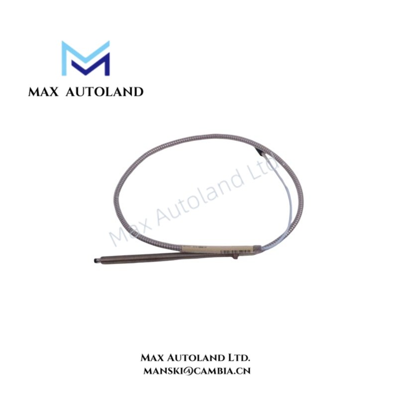
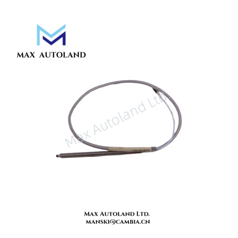
The 109548-01 operates on an eddy-current proximity sensing principle. Its specified nominal scale factor is 7.87 V/mm, with a linear measurement range from 0.25 to 2.30 mm. The specified frequency response extends from 0 to 10 kHz.
The probe is specified for an AISI 4140 steel target. The associated cable has a 75 ohm triaxial impedance, while the specified output resistance is 50 ohm nominal. These electrical characteristics define the signal path between the probe assembly and the associated Proximitor circuitry.
Frequently Asked Questions
Q: What sensing principle does the 109548-01 use?
A: The 109548-01 uses eddy-current proximity sensing for displacement measurement against the specified target material.
Q: What is the specified linear range of the 109548-01?
A: The specified linear range is 0.25 to 2.30 mm, with a nominal scale factor of 7.87 V/mm.
Q: What cable characteristics are specified for this assembly?
A: The supplied configuration is specified with a 75 ohm triaxial cable and a 50 ohm nominal output resistance.
Field Installation Guidelines
Install the probe assembly according to the applicable 3300 XL 8 mm Proximity Transducer installation documentation. Maintain the specified probe-to-target geometry required by the monitoring system.
Route the triaxial cable separately from high-current power wiring and strong electromagnetic noise sources where practical. Avoid unnecessary cable loops and mechanical stress at the probe connection.
Connect the cable and Proximitor circuitry according to the approved wiring configuration. Verify polarity, shielding, and termination before energizing the measurement circuit.
Use the specified target material and verify the physical installation before commissioning. Do not apply an assumed operating temperature, mounting dimension, gap voltage, or cable length when the applicable equipment documentation does not specify it.







Reviews
There are no reviews yet.