

Overview
Hardware Specifications
| Parameter | Specification |
|---|---|
| Model | 128085-01 |
| Brand | Bently Nevada |
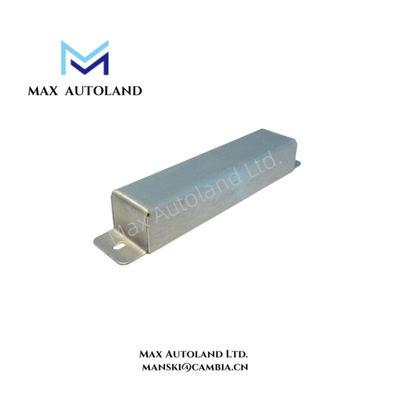
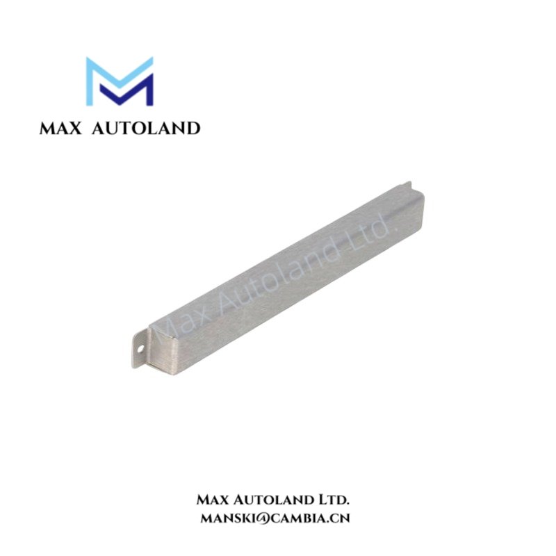
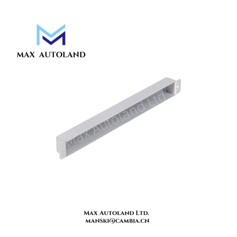
| Product Type | Power Supply Rear Input Connector Cover |
| Series | 3500 Series |
| Associated Module | 3500/15 AC and DC Power Supply |
| Mounting Location | Rear input section of the 3500 rack power supply area |
| Function | Rear input connector protection |
| Associated Hardware | Mounting screws, including referenced 04310251 |
Mechanical Protection and 3500 Rack Interface
The 128085-01 is a passive mechanical component rather than an electronic monitoring module. It interfaces with the rear input area associated with the 3500/15 power supply position.
The cover provides a physical barrier over the rear power input connection area. Therefore, it does not process vibration signals, generate measurement data, or communicate through the 3500 rack backplane.
For machinery protection installations, the cover remains separate from the signal-processing path. Eddy-current probe scaling, gap voltage validation, and rotor dynamics processing occur within the applicable monitoring electronics rather than within this cover.
Frequently Asked Questions
Q: Does the 128085-01 consume rack power?
A: No. The 128085-01 is a passive mechanical cover and has no electrical power consumption.
Q: Does the 128085-01 process vibration or proximity probe signals?
A: No. It provides physical protection for the rear power supply input connection area and does not perform signal processing.
Q: Is the 128085-01 itself a 3500/15 power supply module?
A: No. The 128085-01 is a rear input connector cover associated with the 3500/15 power supply installation area.
Field Installation Guidelines
Install the 128085-01 at the rear input section of the applicable 3500 rack power supply position. Verify that the cover aligns with the intended connector area before securing it.
Use the specified mounting hardware for the installation. The supplied information references mounting screw part number 04310251.
Before installation or removal, follow the site electrical isolation procedure for the associated power supply connections. Do not treat the cover as an electrical disconnect or isolation device.
Route power wiring so that it does not obstruct the cover or place mechanical stress on the connector area. Keep field wiring separated from sensitive monitoring signal wiring according to the site’s electrical installation practice.
Confirm that the cover is mechanically secure after installation and that it does not interfere with adjacent rack wiring, connectors, or service access.


Reviews
There are no reviews yet.