
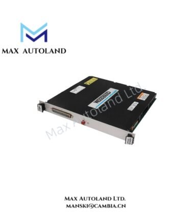
Overview
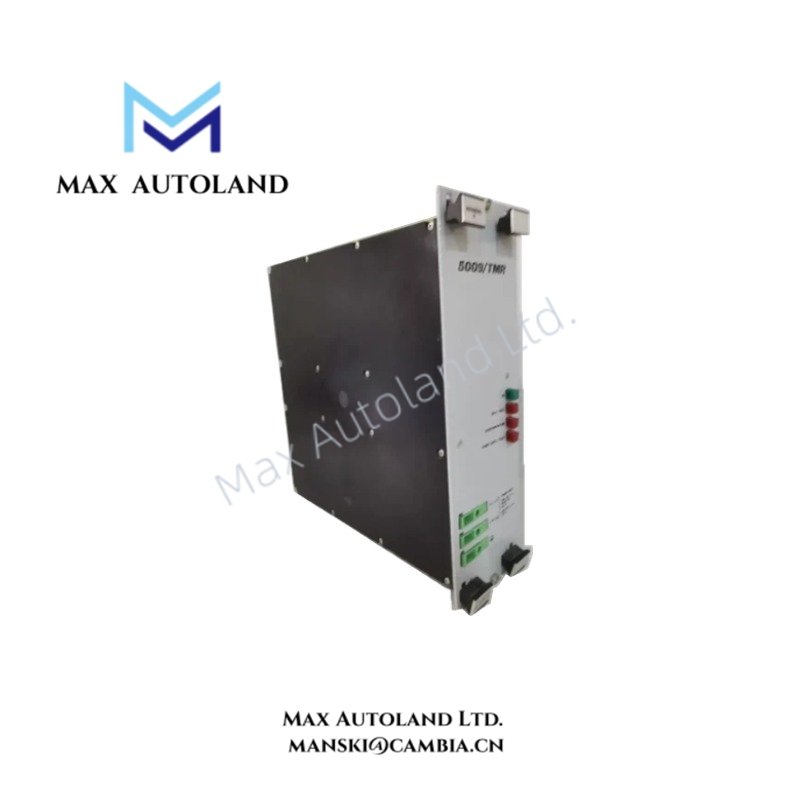
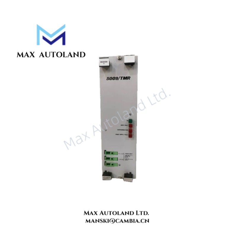
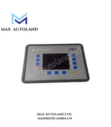
The Woodward 5501-214 (5501-214 Digital Control Module) is described in the supplied information as a controller component for prime mover speed regulation and actuator control. Its specific hardware function, I/O configuration, and compatibility with Woodward control platforms require confirmation from the manufacturer documentation. The listed electrical and environmental values below remain unverified for this exact model.
Hardware Specifications
| Parameter | Specification |
|---|---|
| Model | 5501-214 |
| Brand | Woodward |
| Product Type | Digital Control Modules |
| Operating Temp | Reported as -20 to 65 deg C; not verified |
| Storage Temp | Reported as -40 to 85 deg C; not verified |
| Supply Voltage | Reported as 24 VDC; not verified |
| Discrete Inputs | Configuration and electrical ratings not verified |
| Discrete Outputs | Output type and ratings not verified |
| Speed Sensor Inputs | Supported sensor types not verified |
| Communication Interfaces | RS-232, RS-485, and Ethernet claims require verification |
Governor Control and Actuator Interface Considerations
In a governor control system, the controller processes speed feedback and operating commands to regulate prime mover speed. Depending on the installed hardware configuration, the control system may also manage actuator demand and sequencing.
The supplied information does not establish that the 5501-214 directly provides the listed analog I/O, discrete I/O, speed sensor interfaces, or communication ports. Verify the module identification, terminal assignments, and system compatibility against the applicable Woodward manual before assigning these functions.
For actuator loop commissioning, confirm the configured output signal, actuator input requirements, feedback polarity, and response direction. Validate speed feedback and protective trip logic through the approved commissioning procedure.
Frequently Asked Questions
Q: Does the Woodward 5501-214 support a 24 VDC power supply?
A: The supplied description reports 24 VDC, but this rating has not been verified for the exact model. Check the module nameplate and applicable hardware manual before applying power.
Q: Which input and output signals does the 5501-214 support?
A: The available description mentions analog, discrete, and speed sensor signals. However, the channel count, signal ranges, electrical isolation, and terminal assignments remain unconfirmed.
Q: Can the 5501-214 communicate through Ethernet or RS-485?
A: The supplied description lists Ethernet, RS-232, and RS-485. Confirm the physical interfaces and supported protocols using the manufacturer documentation for the exact part number.
Field Installation Guidelines
- Verify identification: Check the complete part number, hardware revision, nameplate, and intended chassis or controller platform before installation.
- Confirm electrical ratings: Verify supply voltage, polarity, grounding, terminal assignments, and permissible current draw using the applicable manual.
- Inspect signal wiring: Separate low-level sensor wiring from power and switching circuits. Use shielded cables where specified by the manufacturer.
- Apply grounding practices: Terminate cable shields according to the system grounding design. Avoid unintended ground loops.
- Check interface compatibility: Confirm signal ranges, communication interfaces, protocol settings, and connected device requirements before energizing the system.
- Validate operation: Follow the approved startup procedure. Test feedback scaling, actuator response, alarms, and protective interlocks before returning the equipment to service.




Reviews
There are no reviews yet.