

Overview
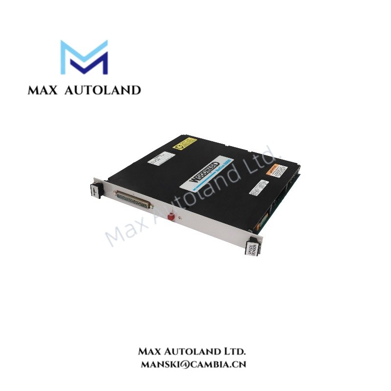
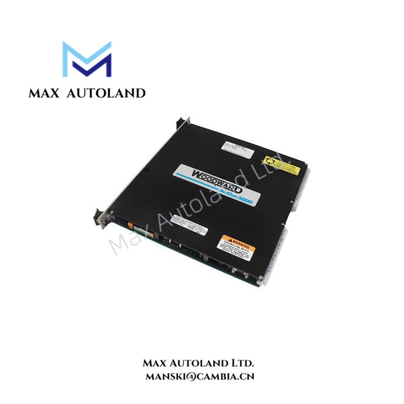
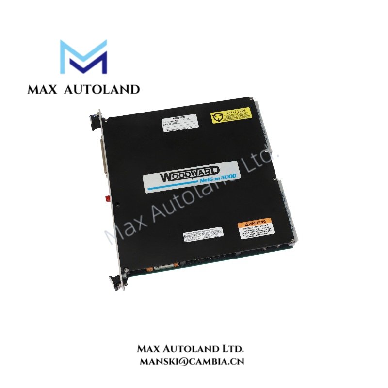
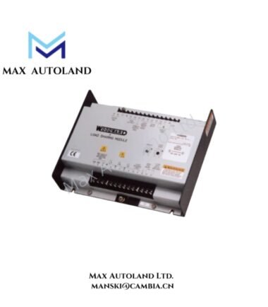
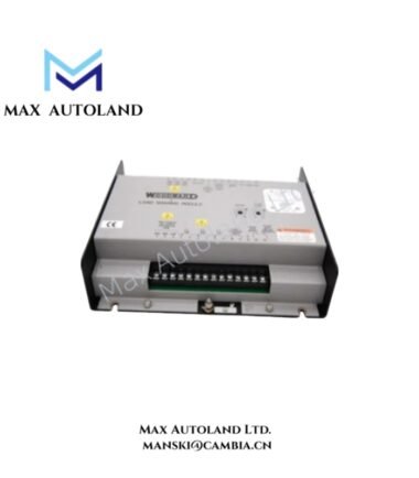
The Woodward 5464-414, also identified by the base model 5464-414, is a digital speed sensing module for processing rotational speed signals within Woodward MicroNet control systems. It is listed as a microprocessor speed sensing component with magnetic pickup and proximity probe inputs. The supplied data identifies a three-channel magnetic pickup configuration and one eddy-current or proximity probe channel.
Hardware Specifications
| Parameter | Specification |
|---|---|
| Model | 5464-414 |
| Brand | Woodward |
| Module Type | Digital Speed Sensor Module |
| Product Description | Digital Microprocessor Speed Sensor |
| System Platform | Woodward MicroNet |
| Input Configuration | 3 magnetic pickup channels and 1 eddy-current / proximity probe channel |
| Weight | 0.96 kg |
| Dimensions | 2.6 x 24.8 x 26.2 cm |
| Operating Temp | 0 to 60 deg C, as supplied |
| Signal Processing | Rotational speed pulse signal processing |
| Part Number | 5464414 / 5464-414 |
Speed Signal Processing and Input Verification
The module is described as processing pulse signals from magnetic pickups or proximity probes for use in speed control applications. The resulting speed feedback can support governor control and speed monitoring when the module is installed in a compatible system configuration.
Before commissioning, verify the input channel assignments, sensor type, signal amplitude, wiring polarity, and configured speed range against the applicable Woodward hardware documentation. Do not assume that every listed sensor type is supported by every input channel without confirming the module specifications.
Frequently Asked Questions
Q: What is the function of the Woodward 5464-414?
A: It is identified as a digital microprocessor speed sensing module intended to process rotational speed signals for a compatible Woodward control system.
Q: Can the 5464-414 accept magnetic pickup and proximity probe signals?
A: The supplied description lists three magnetic pickup channels and one eddy-current or proximity probe channel. Confirm the electrical input requirements and channel configuration using the manufacturer’s documentation before connecting sensors.
Q: What should be checked before replacing this module?
A: Verify the complete part number, hardware revision, chassis compatibility, sensor wiring, input configuration, and system configuration. Confirm the required power supply and operating limits before energizing the replacement.
Field Installation Guidelines
- Isolate the equipment and follow the site’s lockout and tagout procedures before removing or installing the module.
- Confirm the module part number and hardware revision against the system bill of materials.
- Inspect the connector, chassis slot, and terminals for damage or contamination before installation.
- Route sensor signal cables separately from high-current conductors and switching power cables where practicable.
- Apply cable shielding and grounding according to the manufacturer’s installation instructions. Avoid introducing unintended ground loops.
- Verify sensor polarity, signal integrity, and channel assignment before enabling speed control.
- After installation, check diagnostic indications and compare measured speed feedback with an independent reference before returning the controlled equipment to service.



Reviews
There are no reviews yet.