
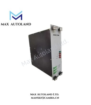
Overview
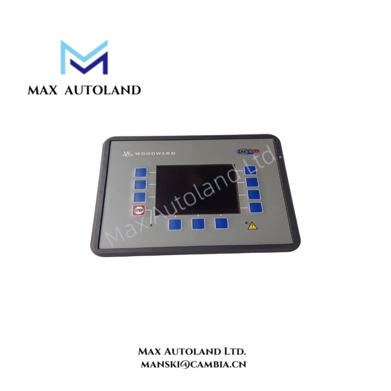
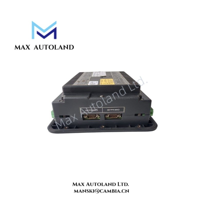
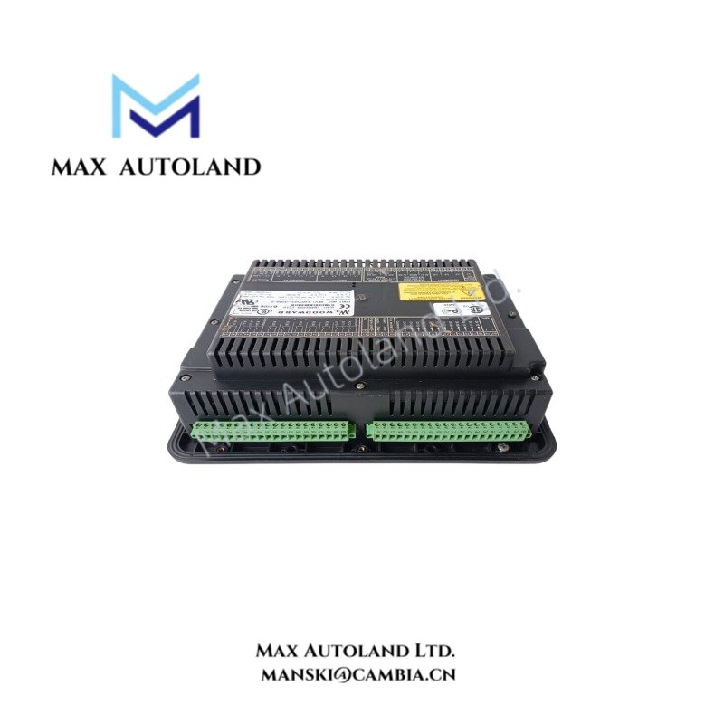
The Woodward 8440-2165, also identified by the base model 8440, is a microprocessor-based synchronizer that measures generator and busbar electrical parameters to coordinate circuit breaker closing during power system paralleling. It evaluates voltage, frequency, and phase conditions to support synchronization control. The unit operates with a 12/24 VDC nominal supply and supports electrical measurement across a 40 to 70 Hz frequency range.
Hardware Specifications
| Parameter | Specification |
|---|---|
| Model | 8440-2165 |
| Brand | Woodward |
| Product Type | Automatic Synchronizer |
| Operating Temp | -20 to 70 deg C |
| Power Consumption | Maximum 10 W |
| Power Supply | 12/24 VDC nominal |
| Supply Voltage Range | 9.5 to 32 VDC |
| Measuring Frequency Range | 40 to 70 Hz |
| Accuracy Class | Class 1 |
| Rated Voltage Options | 66/115 VAC or 230/400 VAC |
| Maximum Voltage | 150 VAC or 300 VAC |
| Rated Phase-to-Ground Voltage | 150 VAC or 300 VAC |
| Rated Surge Voltage | 2.5 kV or 4.0 kV |
| Linear Measuring Range | Up to 1.3 x Vrated |
| Voltage Input Resistance | Approximately 0.21 to 0.696 Mohm |
| Discrete Input Range | 12/24 VDC or 18 to 250 VAC/DC |
| Discrete Input Resistance | Approximately 6.8 kohm or 68 kohm |
| Relay Contact Material | AgCdO |
| General Purpose Relay Rating | 2.00 A at 250 VAC; 2.00 A at 24 VDC; 0.36 A at 125 VDC; 0.18 A at 250 VDC |
| Pilot Duty Relay Rating | 1.00 A at 24 VDC; 0.22 A at 125 VDC; 0.10 A at 250 VDC |
| Ambient Humidity | Up to 95%, non-condensing |
Synchronization Measurement and Actuator Loop Response
The synchronizer evaluates electrical measurements from the generator and busbar to determine synchronization conditions. Its voltage inputs support the specified rated voltage variants, while the measuring frequency range covers 40 to 70 Hz. Discrete inputs provide external control signals, and isolated relay outputs support switching commands within their rated electrical limits.
The generator governor and voltage regulator must respond appropriately to the synchronizer’s control outputs. Verify the configured output functions and control polarity against the applicable wiring diagram before commissioning. Do not assume that all voltage ratings or input configurations apply to every 8440-2165 hardware variant.
Frequently Asked Questions
Q: What DC supply voltage does the Woodward 8440-2165 require?
A: The stated nominal supply is 12/24 VDC, with an operating range of 9.5 to 32 VDC. Maximum intrinsic power consumption is 10 W.
Q: What electrical frequency range can the unit measure?
A: The specified measuring frequency range is 40 to 70 Hz. Confirm that the generator and busbar measurement configuration matches the installed hardware variant.
Q: What limits apply to the relay outputs?
A: General purpose and pilot duty ratings differ by AC or DC voltage and load category. Check the applicable contact rating before connecting a breaker control circuit or an inductive load. Use suitable interposing relays when the external load exceeds the specified contact limits.
Field Installation Guidelines
- Verify the complete model number, terminal assignment, and rated voltage variant against the unit nameplate and applicable Woodward documentation.
- Isolate control power and verify the absence of hazardous voltage before wiring or servicing the equipment.
- Connect generator and busbar voltage measurement circuits to their designated terminals. Confirm phase sequence and voltage transformer ratios before enabling synchronization.
- Route voltage measurement wiring separately from high-current power conductors and switching circuits where practicable.
- Apply the specified protective grounding and shield termination practices from the installation manual. Do not assume that signal shields replace protective earth connections.
- Verify discrete input voltage compatibility before applying external signals.
- Check relay contact ratings against the actual AC or DC load, including the effects of inductive switching.
- Before enabling breaker closing, verify voltage matching, frequency matching, phase sequence, phase angle conditions, and the configured breaker control logic.
- Perform functional tests under controlled conditions before placing the synchronizer into normal service.


Reviews
There are no reviews yet.