

Overview
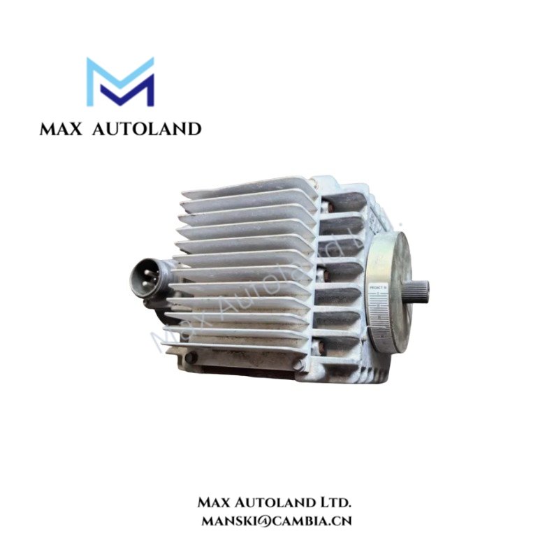
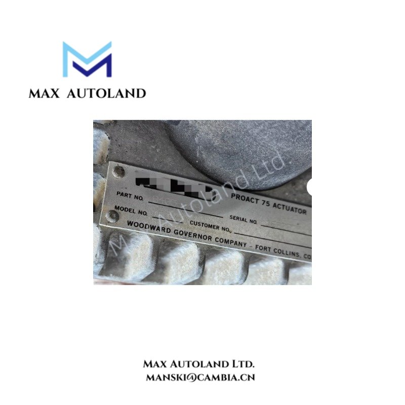
The Woodward 8405-009 is identified in the supplied information as a ProAct 75 electric actuator for mechanical valve positioning. The listed parameters include a 24 VDC power supply, dimensions of 144 x 72 x 122 mm, and a weight of 2.16 lb. Exact actuator performance limits and electrical requirements should be confirmed against the manufacturer’s documentation for this model.
Hardware Specifications
| Parameter | Specification |
|---|---|
| Model | 8405-009 |
| Brand | Woodward |
| Product Type | Electric Actuator |
| Series | ProAct 75 |
| Origin | USA |
| Weight | 2.16 lb |
| Dimensions | 144 x 72 x 122 mm |
| Operating Temp | -40 to +85 deg C |
| Power Supply | 24 VDC |
| Operating Pressure | Up to 75 psi |
| Steady-State Power | 8 to 101 W |
| Transient Power | 32 to 371 W |
Actuator Loop Feedback and Positioning
An electric actuator converts an electrical command into mechanical movement. In a governor or valve-control loop, the controller output must match the actuator’s electrical input requirements. The actuator’s mechanical travel, load characteristics, feedback signal, and response limits must also match the application.
The supplied information does not establish the command signal type, feedback interface, travel range, or control-loop response specifications for model 8405-009. Confirm these parameters before integrating the actuator into a control system.
Frequently Asked Questions
Q: Can the 8405-009 operate from a 24 VDC supply?
A: The supplied data lists 24 VDC. Verify the permitted voltage range, current demand, and transient requirements in the applicable manufacturer documentation.
Q: What is the maximum operating temperature?
A: The supplied range is -40 to +85 deg C. Confirm this range against the exact model’s official datasheet before installation.
Q: Can the actuator connect directly to a PLC or governor output?
A: Compatibility depends on the actuator’s command input, electrical load, feedback interface, and controller output type. Verify the wiring diagram and electrical specifications before connecting the unit.
Field Installation Guidelines
- Verify the complete model number and nameplate information before installation.
- Confirm the supply voltage, polarity, protective device requirements, and available current.
- Check the mechanical coupling, mounting alignment, and valve travel limits.
- Separate actuator power wiring from low-level feedback and communication wiring where practical.
- Follow the manufacturer’s grounding and cable-shield termination instructions.
- Verify the command and feedback signals before enabling closed-loop operation.
- Perform a controlled functional test to confirm movement direction, travel limits, and response to controller commands.
- Do not use the listed pressure or power ranges as design limits until the original specifications are verified.


Reviews
There are no reviews yet.