
Overview
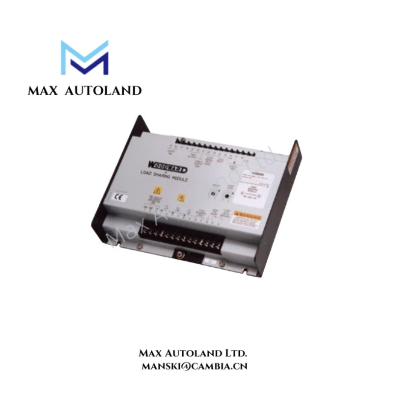
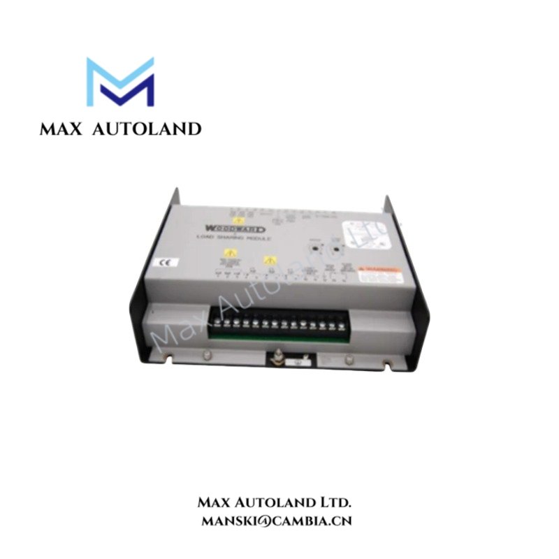
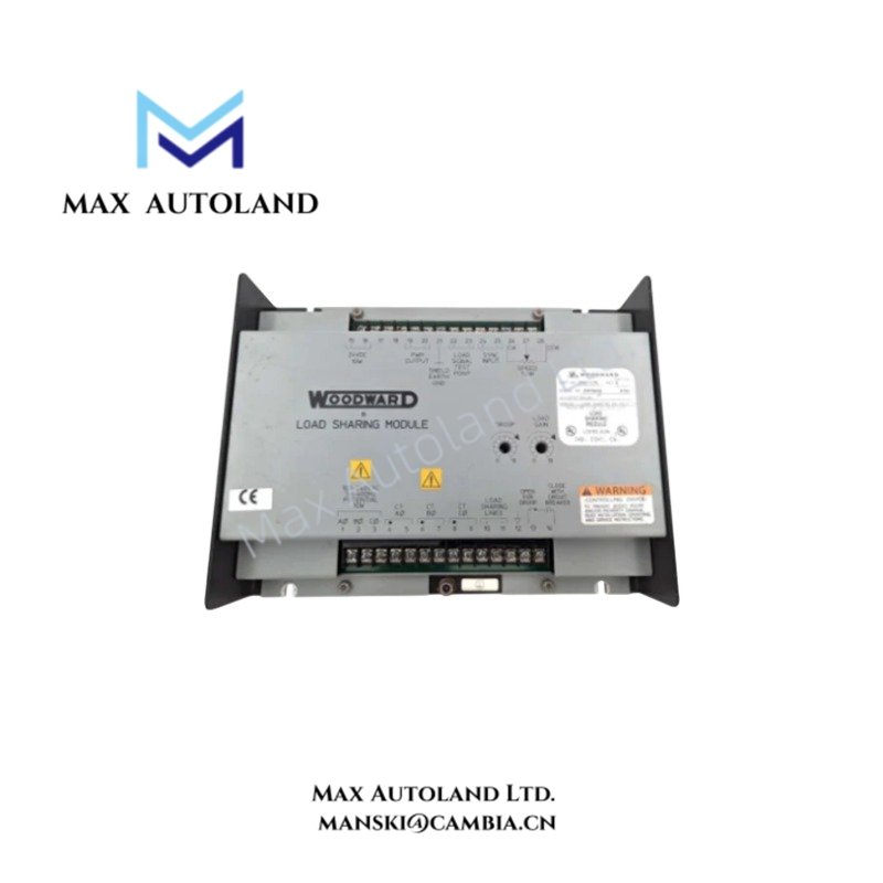
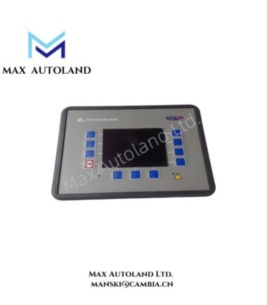
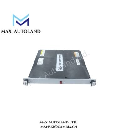
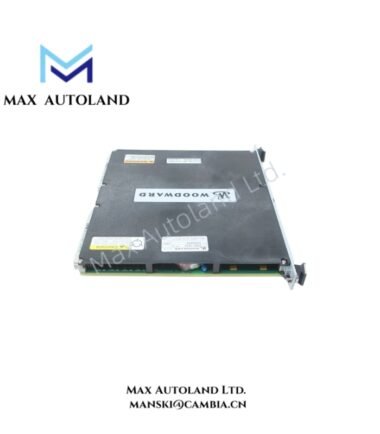
The Woodward 5453-759, also cataloged as the 5453-759 MicroNet-Plus 14-Slot Chassis, provides the physical mounting and interconnection structure for compatible control and communication modules within a MicroNet-Plus turbine control system. It supports modular hardware installation. Electrical loading, module compatibility, and power distribution depend on the installed configuration.
Hardware Specifications
| Parameter | Specification |
|---|---|
| Model | 5453-759 |
| Brand | Woodward |
| Product Type | MicroNet-Plus 14-Slot Chassis |
| Origin | United States |
| Weight | Approx. 3 lbs (1.36 kg) |
| Dimensions | 16 x 16 x 12 cm |
| Slot Count | 14 |
| System Platform | MicroNet-Plus |
| Application | Turbine control hardware mounting and interconnection |
Chassis Integration and Governor Control Architecture
The 5453-759 provides a mechanical framework for installing compatible MicroNet-Plus control hardware. Its role differs from that of a processor, I/O module, or governor output module, which performs specific control functions.
Woodward turbine control systems use configured hardware to process control inputs and execute governor functions. The chassis itself should not be assumed to provide independent signal processing, actuator feedback control, or communication protocol conversion.
Before installation, verify the chassis revision, module compatibility, backplane connections, and power distribution requirements against the applicable Woodward documentation. Do not assume hot-swap support or redundant operation without configuration-specific confirmation.
Frequently Asked Questions
Q: How many module positions does the Woodward 5453-759 provide?
A: The supplied product description identifies 14 module slots. Confirm the supported module arrangement using the system hardware documentation.
Q: What electrical load can the chassis backplane support?
A: The maximum backplane current and power distribution limits are not specified in the supplied data. Check the chassis documentation and calculate the combined load of the installed modules before energizing the system.
Q: Can installed modules be replaced while the system is energized?
A: Hot-swap capability is not confirmed by the available information. Follow the documented shutdown and module replacement procedure for the specific MicroNet-Plus configuration.
Field Installation Guidelines
- Verify the chassis part number and revision before installation.
- Inspect the chassis, connectors, and backplane contacts for mechanical damage or contamination.
- Secure the chassis to a suitable mounting structure using the specified hardware.
- Confirm that each installed module is compatible with the chassis and system configuration.
- Verify power supply ratings and total module load before applying power.
- Route control wiring separately from high-current switching and motor power cables where practical.
- Apply protective earth and cable shield termination according to the equipment documentation and site grounding standards.
- Do not energize the system if connector damage, incorrect module placement, or uncertain power distribution conditions remain unresolved.


Reviews
There are no reviews yet.