



Overview
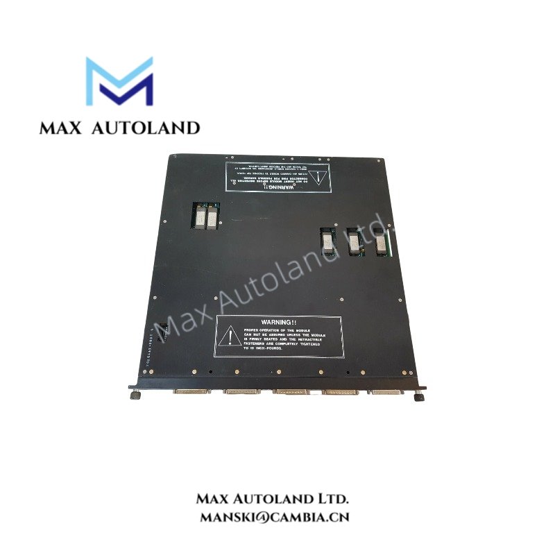
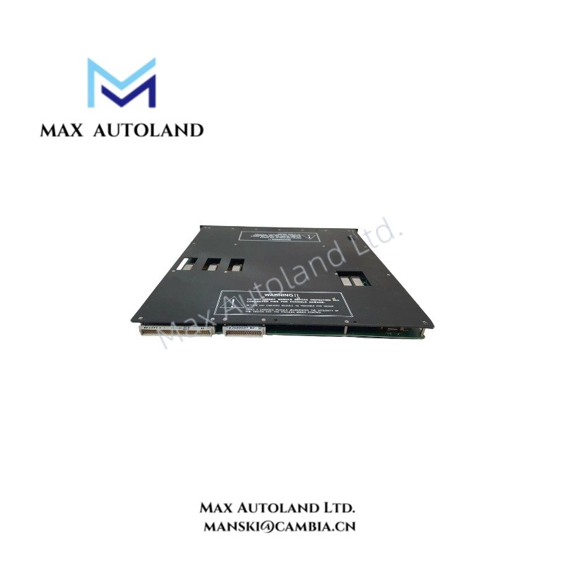
Configured for high-integrity pulse-generating signal execution in Triconex Triple Modular Redundant systems, the Triconex 4118, also cataloged as the 4118 Pulse Input Module, delivers direct physical and electrical processing.
Suffix Breakdown & Model Matrix
| Suffix Identifier | Hardware Variation | Functional Scope |
|---|---|---|
| 4118 | Standard PIM | 8-channel pulse input with optical isolation and TMR architecture support |
Hardware Specifications
| Parameter | Specification |
|---|---|
| Model | 4118 |
| Brand | Triconex |
| Origin | United States / Global Manufacturing Facilities |
| Weight | Approximately 1.5 kg |
| Dimensions | Standard Triconex Eurocard form factor |
| Operating Temp | 0 deg C to 60 deg C |
| Power Consumption | Derived from Triconex chassis backplane |
| Number of Channels | 8 isolated input channels |
| Input Compatibility | Magnetic pickups, proximity switches, contact closure devices |
| Isolation | Channel-to-channel and channel-to-ground optical isolation |
Triple Modular Redundancy And Fault Tolerant Execution
Operating directly within a TMR architecture framework, the module executes 2oo3 voting logic across redundant processing channels. Furthermore, internal circuitry continuously monitors input signal integrity and hardware status through self-diagnostics. Galvanic and optical isolation safeguard internal data buses against external electrical noise and ground loops. Consequently, the system architecture automatically masks single-point hardware anomalies, thereby preventing any operational disruption.
Frequently Asked Questions
Q: Does the Triconex 4118 support hot-swap replacement during active system operation?
A: Yes, engineers can replace the module online under specific safety and procedural guidelines defined in the system manual, provided that they maintain system redundancy.
Q: How do technicians protect input signals against electromagnetic interference in industrial environments?
A: Technicians rely on integrated channel-to-channel and channel-to-ground optical isolation alongside shielded twisted-pair cabling requirements to suppress induced noise effectively.
Field Installation Guidelines
First, ensure that technicians disconnect all power from the target chassis slot before attempting physical insertion or removal. Next, terminate incoming signal lines from magnetic pickups and proximity switches into the designated terminal blocks while maintaining proper shield grounding to minimize transient voltage coupling. Finally, verify that front-panel diagnostic indicators display healthy communication and channel activity upon system startup.
Triconex Top Products
| Triconex | Triconex | Triconex |
| 3625 | CM3201 | 4211 |
| 3700A | 7400207-001 | 9662-810 |
| 4329 | 7400209B-030 | 9563-810 |
| 3008 | 7400208C-020 | 9753-110 |
| 4119A | 7400209-030 | 9853-610 |
| 3636T | 8306A | 9761-210 |
| 3805E | 3625C1 | 4351B |
| 4351A | 3481 S2 | 3721 |
| DO3401 | 4210 | 8312 |
| DI3301 | 8111 | 3503E |
| 3664 | 9562 3000520-390 | MP3101 |


Reviews
There are no reviews yet.