
Overview
Hardware Specifications
| Parameter | Specification |
|---|---|
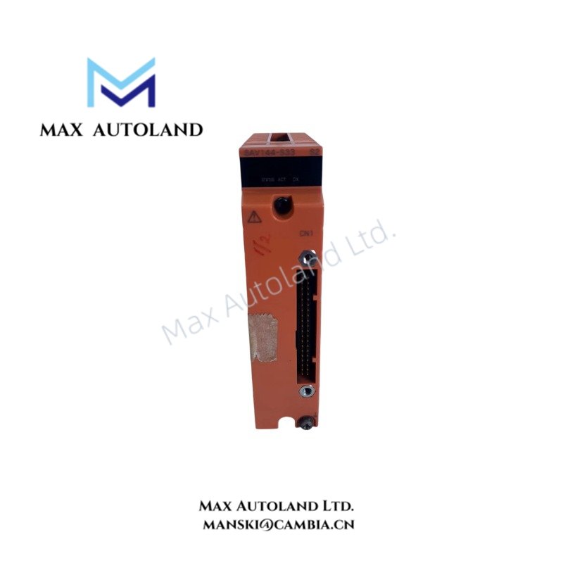
| Model | SAV144 |
| Brand | Yokogawa |
| Module Type | Voltage Input Module |
| Number of Input Channels | 16 |
| Input Isolation | Module-isolated |
| Rated Input Range | 1 to 5 VDC / 1 to 10 VDC |
| Permissible Input Range | +/- 30 VDC |
| Input Impedance (Power On) | 100 kohm |
| Rated Accuracy (1 to 5 V) | +/- 4 mV |
| Rated Accuracy (1 to 10 V) | +/- 9 mV |
| Data Update Frequency | 40 ms |
| Withstand Voltage | 1.5 kVAC between input signal and system for 1 minute |
| Maximum Current Consumption (5 V System) | 300 mA |
| Maximum Current Consumption (24 V System) | 140 mA |
| Redundancy | Single or dual-redundant configurations |
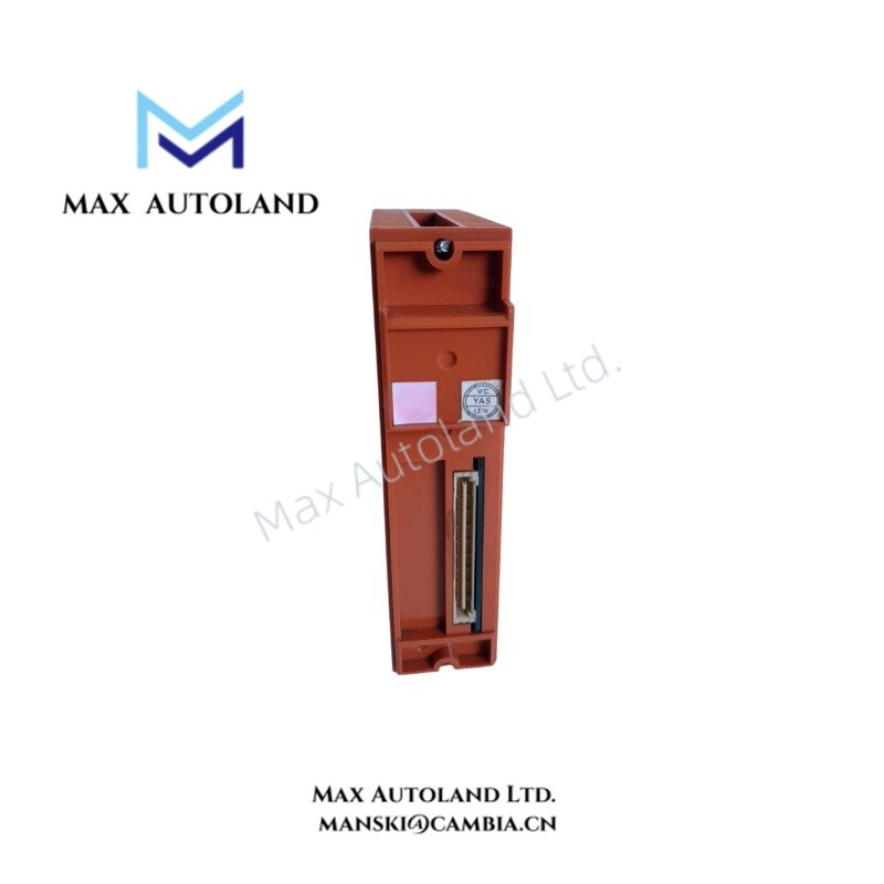
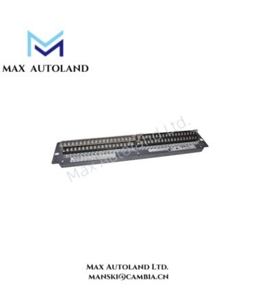
| External Connections | Pressure clamp terminal blocks, MIL cables, or dedicated signal cables such as KS1 |
| Weight | Approximately 0.24 kg to 0.29 kg |
Analog Voltage Acquisition and Channel Isolation
The SAV144 processes voltage signals within its specified rated input ranges. The permissible input range extends to +/- 30 VDC; this value does not replace the rated measurement range.
Module-level isolation separates the input circuitry from the system side. The specified withstand voltage is 1.5 kVAC for one minute between the input signal and system. The supplied data does not establish channel-to-channel galvanic isolation.
The 40 ms data update frequency defines the stated update interval. Actual control response also depends on the host system configuration and application processing.
Frequently Asked Questions
Q: Can the SAV144 accept input voltages up to 30 VDC as its normal measurement range?
A: No. The rated input ranges are 1 to 5 VDC and 1 to 10 VDC. The +/- 30 VDC specification identifies the permissible input range, not the rated measurement range.
Q: What current does the SAV144 draw from the system power supplies?
A: The supplied specifications list maximum current consumption of 300 mA for the 5 V system and 140 mA for the 24 V system. Confirm the applicable supply rail and system loading requirements before installation.
Q: Does the SAV144 support dual-redundant operation?
A: The supplied data lists single and dual-redundant configurations. Confirm the required host-system architecture, module pairing, and applicable installation rules before configuring redundancy. Switching time is not specified in the supplied data.
Field Installation Guidelines
- Verify the complete module model and suffix against the applicable Yokogawa hardware documentation before installation.
- Confirm the host-system compatibility, slot assignment, and redundancy requirements.
- Check the field signal range before connecting transmitters or other voltage sources.
- Route analog signal wiring separately from high-voltage power conductors and high-noise switching circuits.
- Apply cable shielding and grounding according to the system installation manual. Avoid creating unintended ground loops.
- Verify terminal block or cable compatibility before wiring. The supplied data identifies pressure clamp terminals, MIL cables, and dedicated signal cables as connection options.
- Check the power supply loading against the specified current consumption for the applicable voltage rail.
- Do not apply signals outside the permitted electrical limits. Confirm the input wiring and signal polarity before energizing the system.
YOKOGAWA Top Products
Customers Also Viewed



Reviews
There are no reviews yet.