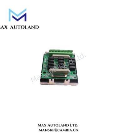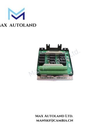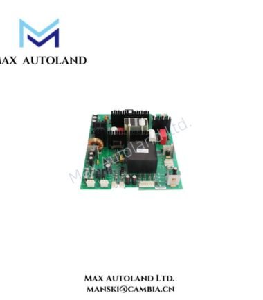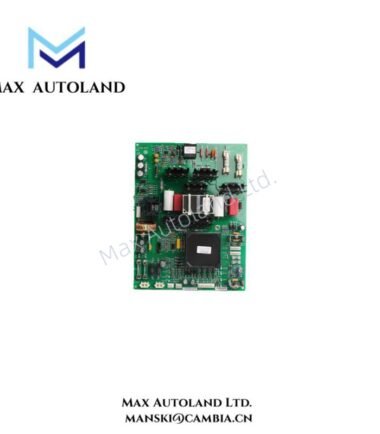

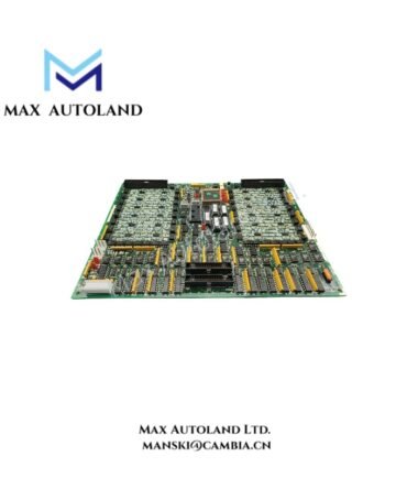
Overview
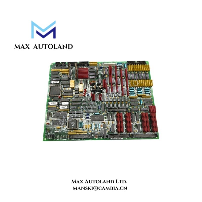
The GE DS200TCQAG1BHF-W01, associated with the DS200TCQAG1BHF base model designation, is an analog I/O board identified for the GE Mark V turbine control system. It is described as an RST analog input/output board for processing analog signals between field devices and the control system. The supplied data lists 0-10 VDC input and output ranges; however, the exact channel configuration and electrical specifications require confirmation against the applicable board documentation.
Hardware Specifications
| Parameter | Specification |
|---|---|
| Model | DS200TCQAG1BHF-W01 |
| Base Model | DS200TCQAG1BHF |
| Brand | General Electric (GE) |
| Product Series | Mark V |
| Product Type | Analog I/O Board |
| Board Classification | RST Analog Input/Output Board |
| Origin | USA |
| Weight | 0.58 kg |
| Dimensions | 27.8 x 21.2 x 2.2 cm |
| Operating Temp | 0 deg C to +60 deg C |
| Storage Temp | -40 deg C to +85 deg C |
| Relative Humidity | 5% to 95%, non-condensing |
| Input Voltage Range | 0-10 VDC |
| Output Voltage Range | 0-10 VDC |
| Resolution | 12 bits |
| Number of Channels | 8 |
| Communication Interface | RS-485 |
| HS Code | 8537101190 |
Mark V Analog Signal Processing
The reported analog input and output ranges describe voltage-based signal handling. Before integrating the board into a Mark V rack, verify the supported signal types, channel assignments, connector pinout, and interface requirements against the board revision documentation. Do not assume that the listed 0-10 VDC ranges, 12-bit resolution, eight-channel configuration, or RS-485 interface apply to every DS200TCQAG1BHF-W01 configuration without confirmation.
Mark V hardware integration also requires compatibility checks for rack connections, control-system configuration, and the applicable board revision. Confirm the correct replacement designation before substituting a board.
Frequently Asked Questions
Q: What operating temperature should be used for this board?
A: The supplied data contains two different operating temperature ranges: -20 deg C to +70 deg C and 0 deg C to +60 deg C. The applicable range has not been verified. Check the manufacturer’s documentation for the exact board revision before defining the installation limits.
Q: What is the board’s power consumption?
A: The supplied information does not specify power consumption or rack supply current. Confirm the required supply rails and current draw using the applicable hardware documentation before calculating rack power loading.
Q: Can the board be replaced without changing the control-system configuration?
A: Compatibility depends on the exact board part number, revision, connector arrangement, and control-system configuration. Verify these details before replacement. The supplied information does not establish hot-swap support or configuration interchangeability.
Field Installation Guidelines
- Verify the hardware identity. Check the complete DS200TCQAG1BHF-W01 designation and the board revision against the equipment documentation.
- Isolate power. Follow the site’s approved shutdown and lockout procedures before removing or installing the board.
- Inspect connections. Check rack connectors, ribbon cables, terminals, and mating contacts for damage, contamination, or loose connections.
- Control electrostatic discharge. Use appropriate ESD protection when handling the circuit board.
- Separate signal wiring. Route analog signal cables away from high-current conductors and sources of electrical interference where practical. Follow the system wiring drawings and applicable shielding requirements.
- Check grounding and shielding. Apply the grounding arrangement specified by the manufacturer. Avoid creating unintended ground loops.
- Verify configuration. Confirm channel assignments, signal ranges, rack position, and control-system compatibility before energizing the equipment.
- Test after installation. Check signal readings, output behavior, alarms, and diagnostic indications against approved commissioning procedures.