


Overview
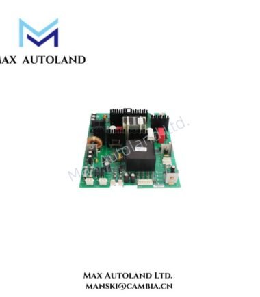
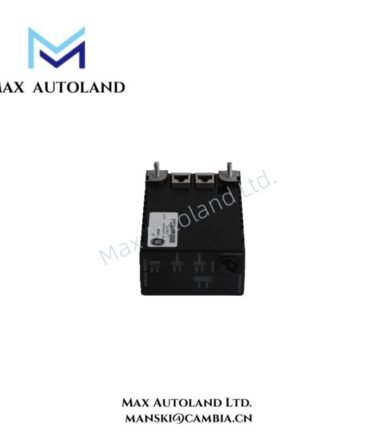
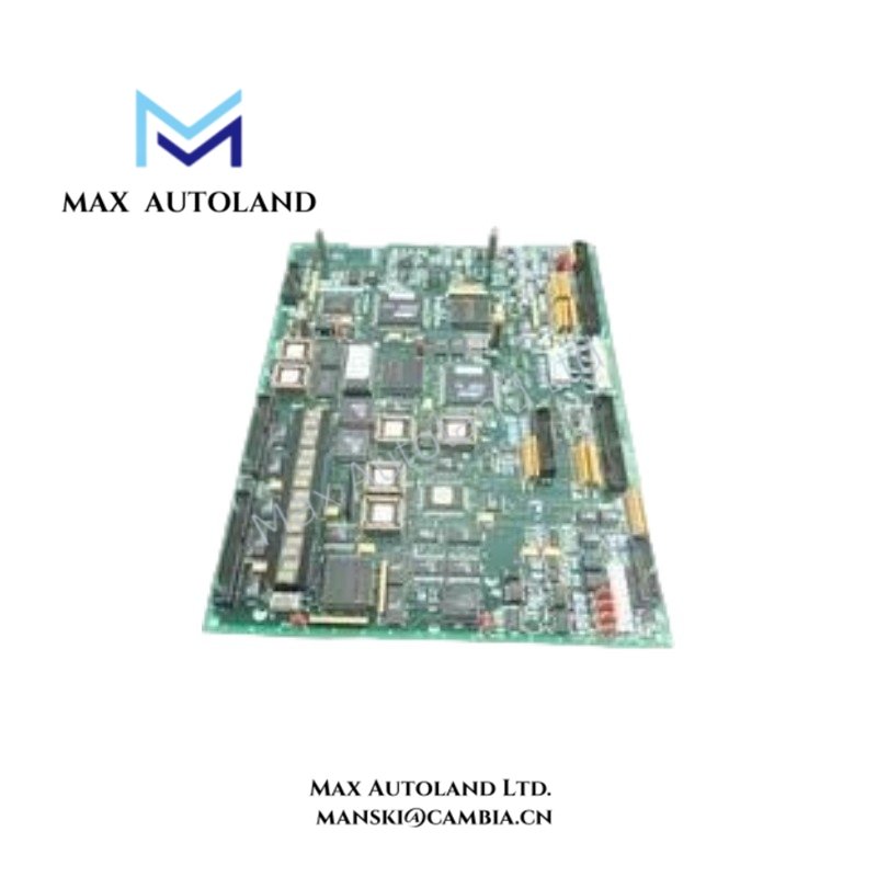
The GE DS200PCCRG1ACB, associated with the DS200PCCRG1A base model, is identified in the supplied description as a printed circuit board for the GE Mark V control platform. The exact electrical function of this revision requires confirmation from manufacturer documentation. The available information does not establish its signal interfaces, power ratings, or backplane communication characteristics.
Hardware Specifications
| Parameter | Specification |
|---|---|
| Model | DS200PCCRG1ACB |
| Brand | GE |
| Series | Mark V / Speedtronic |
| Board Type | Printed Circuit Board |
| Origin | USA |
| Core Function | Exact electrical function not verified |
| Tariff Code | 8537101190 |
Industrial Control Hardware and Interface Verification
GE control boards can use platform-specific electrical interfaces, backplane connections, and revision-dependent hardware configurations. However, the available data does not confirm the DS200PCCRG1ACB’s bus protocol, I/O density, power distribution function, or firmware compatibility.
Therefore, verify the complete board number, revision markings, connector arrangement, and applicable GE hardware documentation before selecting a replacement. Do not assume compatibility based only on the DS200PCCRG1A base designation.
Frequently Asked Questions
Q: Can the DS200PCCRG1ACB be replaced with another DS200PCCRG1A revision?
A: Not without verification. Compare the complete part number, revision, connector layout, electrical ratings, and manufacturer-approved replacement information.
Q: What power supply and backplane load does this board require?
A: The available information does not specify supply voltage, current consumption, or backplane loading. Obtain these values from the applicable GE hardware documentation before installation.
Q: Is the DS200PCCRG1ACB hot-swappable?
A: Hot-swap support is not established by the supplied information. Follow the equipment-specific isolation and replacement procedures, and do not remove the board while energized unless the manufacturer explicitly permits it.
Field Installation Guidelines
- Verify the full model number and revision against the equipment bill of materials and applicable GE documentation.
- Isolate the relevant power sources and confirm a safe electrical state before handling the board.
- Inspect the PCB, connectors, and mating interfaces for physical damage, contamination, or corrosion.
- Use appropriate electrostatic discharge (ESD) protection when handling the board.
- Keep wiring and connectors aligned with the documented terminal and interface assignments. Do not infer pinouts from visual similarity.
- Confirm power requirements, grounding arrangements, and approved configuration settings before energizing the equipment.
- After installation, follow the system commissioning procedure and check for diagnostic alarms or abnormal indications.