
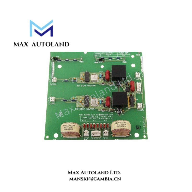

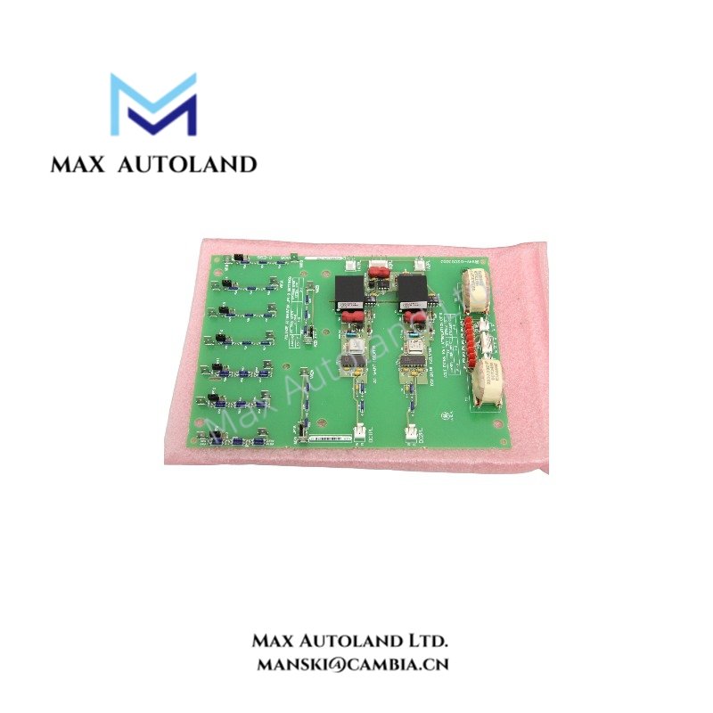


Overview
The GE DS200SHVMG1AGE, also identified by the base model DS200SHVMG1, is described in the supplied information as an interface board for the GE Speedtronic Mark V control system. Its exact signal-routing function, electrical interfaces, and rack compatibility require confirmation against the manufacturer documentation. The supplied data does not establish specific isolation ratings, channel configurations, or backplane current requirements.
Hardware Specifications
| Parameter | Specification |
|---|---|
| Model | DS200SHVMG1AGE |
| Brand | General Electric (GE) |
| Product Series | Speedtronic Mark V |
| Board Type | Interface Board |
| Origin | USA |
| Operating Temp | 0 to 60 deg C |
| Storage Temp | -40 to 85 deg C |
| Operating Humidity | 5% to 95% non-condensing |
| Operating Voltage | Rack-supplied voltage stated in the supplied data |
| Compatibility | GE Speedtronic Mark V |
| Mounting Type | Plug-in rack mounting stated in the supplied data |
Backplane Interface and Electrical Compatibility
The DS200SHVMG1AGE requires a verified electrical interface before engineers connect it to a control rack. First, check the applicable GE drawings for connector assignments, supply rails, and signal paths. In addition, confirm the board revision and system configuration before replacing an existing unit.
- Backplane connections: Check the connector layout and signal assignments against the relevant system drawings.
- Power requirements: The supplied description mentions +5 VDC and +/-15 VDC. However, these values do not confirm the board’s actual supply requirements.
- Signal integrity: Keep sensitive signal cables separate from high-current switching conductors where the cabinet layout allows.
- Revision compatibility: Compare the complete part number and board revision before installation.
Frequently Asked Questions
Q: Can the DS200SHVMG1AGE fit any GE Mark V rack?
A: Do not assume universal compatibility. Instead, check the connector layout, rack position, and applicable GE documentation before installation.
Q: What voltage and current does this board require?
A: The supplied description lists +5 VDC and +/-15 VDC as possible rack voltages. However, it does not confirm the board’s exact voltage requirements or current consumption. Consult the applicable technical drawings before connecting power.
Q: Can engineers replace this board while the system is running?
A: The supplied data does not confirm hot-swap support. Therefore, follow the approved shutdown and replacement procedure unless GE documentation explicitly permits live replacement for the target configuration.
Field Installation Guidelines
- First, isolate the relevant equipment according to the site’s electrical safety procedures.
- Next, compare the full part number, board revision, connector orientation, and rack position with the existing assembly.
- Then, inspect the connectors for bent contacts, contamination, or physical damage.
- Route signal cables away from power conductors where practical. Also, follow the cabinet’s grounding and cable-shield requirements.
- Before restoring operation, check connector seating and verify the supply conditions against approved documentation.
- Finally, review system diagnostics and confirm the interface signals using the site’s commissioning procedures.


