
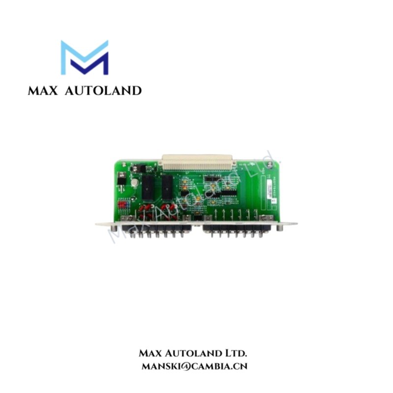
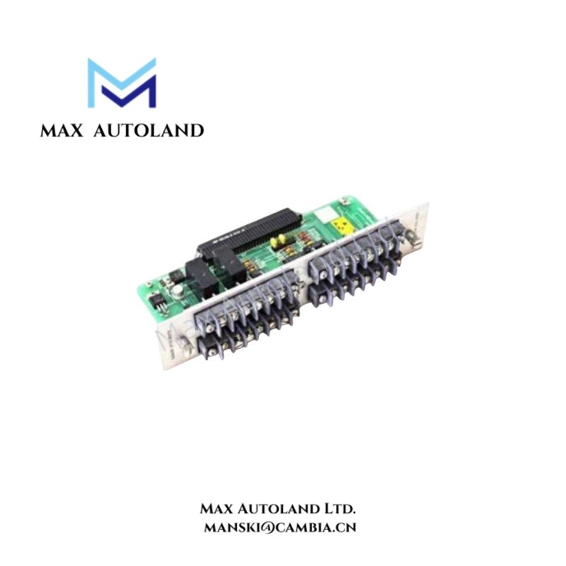
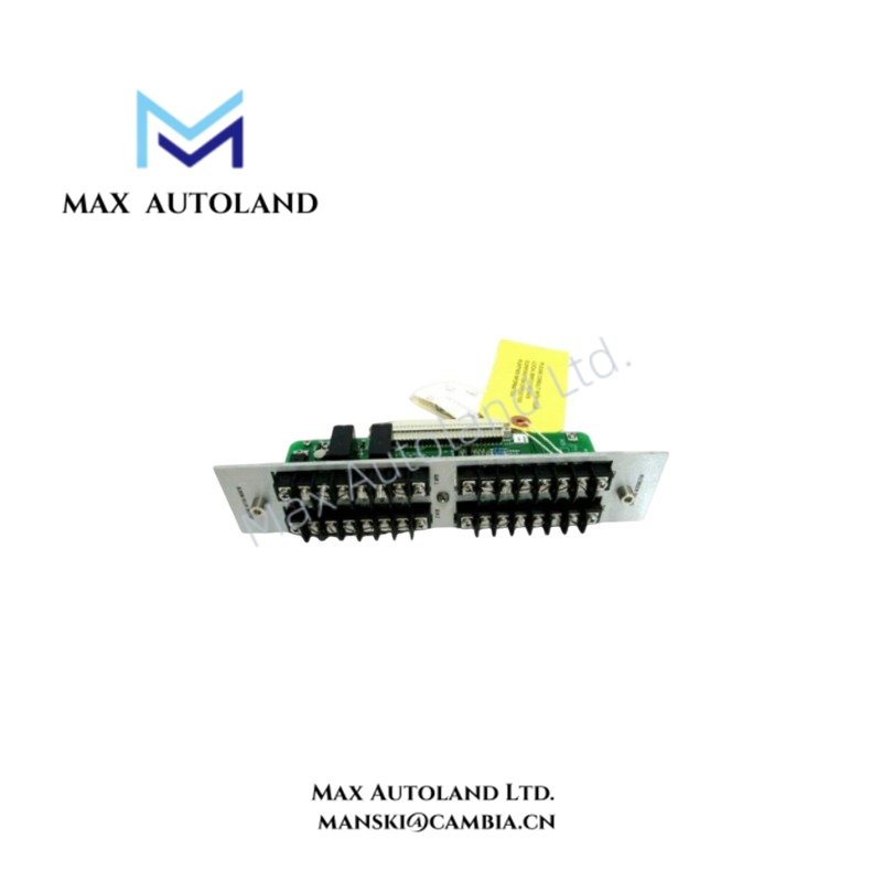
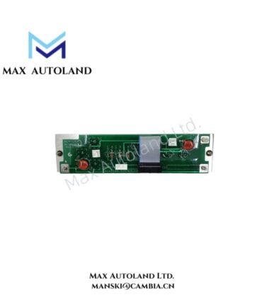
Overview
Hardware Specifications
| Parameter | Specification |
|---|---|
| Model | 84134-01 |
| Brand | Bently Nevada |
| Product Family | 3300 Series |
| Compatible Monitor | 3300/55 Dual Velocity Monitor |
| Component Type | Printed Wiring Assembly (PWA) |
| Signal Type | Velocity transducer signals |
| Input Configuration | Dual-channel velocity inputs |
| Sensor Compatibility | Velocity transducers, Seismoprobes, Velomitor sensors |
| Output Type | Proportional recorder outputs |
| Output Range | Typically 4-20 mA, according to monitor configuration |
| Primary Function | Velocity signal processing and machinery vibration monitoring |
Mechanical Vibration Signal Processing
The 84134-01 PWA forms part of the signal path associated with the 3300/55 Dual Velocity Monitor. The monitor receives velocity-related signals from connected transducers and processes the channel information for casing and structural vibration monitoring.
For field wiring, each velocity channel should maintain its intended signal path and cable shielding arrangement. Signal cables should be routed separately from high-current power conductors and other high-noise circuits where practical. This reduces the possibility of electrical interference and channel cross-talk entering the vibration measurement path.
The proportional recorder output represents the monitored channel value according to the configured monitor range. Actual scaling depends on the associated 3300/55 system configuration and should be verified against the applicable system documentation.
Frequently Asked Questions
Q: Is the 84134-01 a complete standalone velocity monitor?
A: No. The 84134-01 is identified as a Printed Wiring Assembly used as an internal circuit-board component of the 3300/55 Dual Velocity Monitor system.
Q: How many velocity channels are associated with the supported monitor configuration?
A: The supplied information identifies the 3300/55 as a dual velocity monitor with two velocity input channels.
Q: Does the 84134-01 directly define the 4-20 mA output scaling?
A: The supplied data identifies proportional recorder outputs, typically 4-20 mA. The actual scaling is determined by the associated monitor configuration and range settings.
Field Installation Guidelines
- Verify the board identification and 84134-01 part number before installation.
- Install the PWA only in the specified 3300/55 system position.
- Disconnect system power before accessing internal monitor electronics.
- Confirm connector orientation and seating before restoring power.
- Maintain separation between vibration signal wiring and high-current or high-noise conductors.
- Terminate cable shields according to the applicable 3300 Series installation documentation.
- Do not alter recorder-output scaling without verifying the associated monitor configuration.
- After installation, verify both velocity channels and their associated signal indications before placing the monitoring channel into service.




Reviews
There are no reviews yet.