



Overview
Hardware Specifications
| Parameter | Specification |
|---|---|
| Model | 128329-01 |
| Brand | Bently Nevada |
| Product Series | 3500 Series Monitoring System |
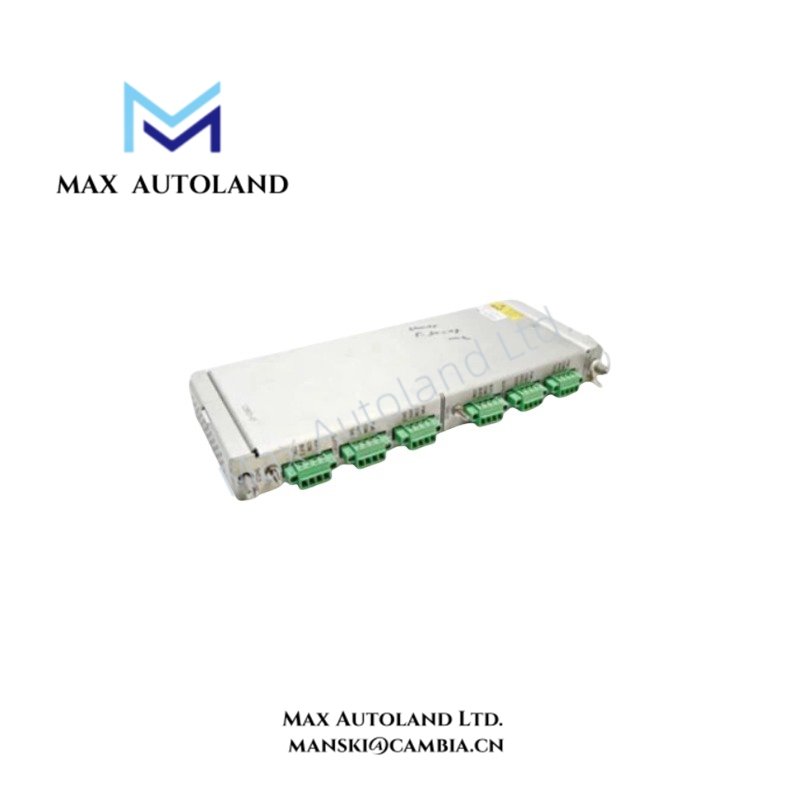
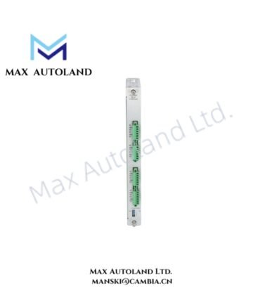
| Module Type | Prox/Seismic Input/Output Module |
| Compatible Monitor | 3500/42M Proximitor Seismic Monitor |
| Termination | Internal Terminations, non-barrier |
| Input Signals | Proximity and seismic transducer signals |
| Installation Position | Rear slot of 3500 rack |
| Operating Temp | -30 deg C to +65 deg C |
| Storage Temp | -40 deg C to +85 deg C |
| Relative Humidity | Up to 95%, non-condensing |
Eddy-Current and Seismic Signal Interface
The 128329-01 provides the field termination path for transducer signals associated with proximity and seismic measurements. For eddy-current proximity systems, the connected probe and Proximitor electronics establish the electrical signal representing shaft position or vibration. The 3500/42M then processes the acquired signal according to its configured monitoring functions.
For seismic inputs, the interface can accommodate signals from compatible seismic transducers such as accelerometers or velocity transducers. Signal routing should maintain separation from high-current and high-voltage wiring to limit electrical interference and unwanted cross-talk.
Frequently Asked Questions
Q: Is the 128329-01 a standalone vibration monitor?
A: No. It is an I/O module used with the 3500 rack and compatible monitoring hardware such as the 3500/42M.
Q: Does the 128329-01 use internal or external field termination?
A: The supplied specification identifies it as an internal-termination, non-barrier I/O configuration.
Q: What type of signals does the module interface?
A: It interfaces compatible proximity and seismic transducer signals for acquisition by the associated 3500 monitoring module.
Field Installation Guidelines
Install the 128329-01 in the designated rear position of the 3500 rack and verify compatibility with the associated monitor and rack configuration before wiring.
Route transducer wiring separately from power conductors and other high-level signal circuits. Maintain appropriate cable shielding and terminate shields according to the system grounding design. Avoid creating unintended ground loops through multiple shield termination points.
For eddy-current probe circuits, verify probe, Proximitor, cable, and monitor compatibility before energizing the measurement channel. Check the expected signal path and gap-voltage condition against the applicable system documentation.
For seismic transducers, confirm sensor type and signal interface before connection. Do not apply field wiring to an incompatible channel configuration.








Reviews
There are no reviews yet.