

Overview
Hardware Specifications
| Parameter | Specification |
|---|---|
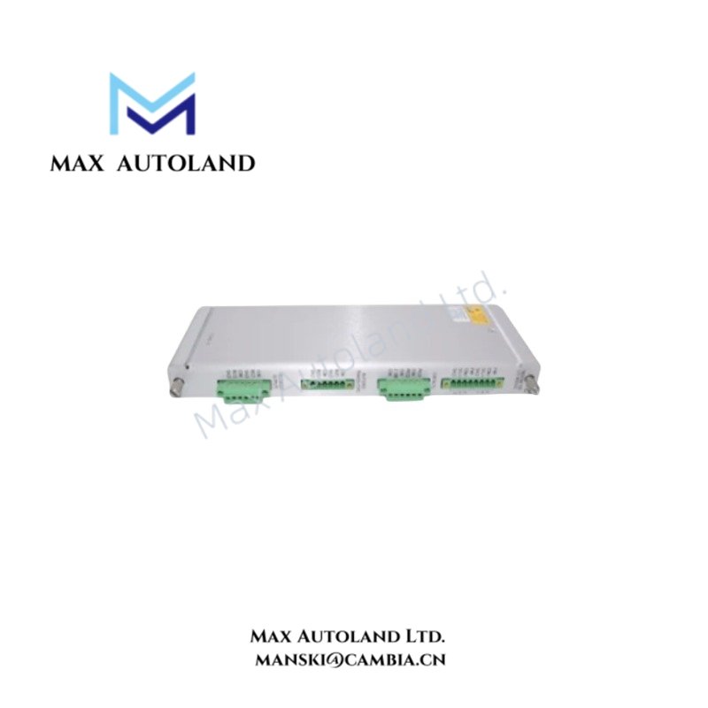
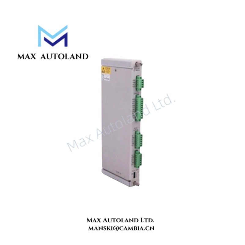
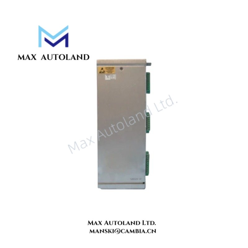
| Model | 124240-01 |
| Brand | Bently Nevada |
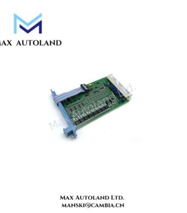
| Product Type | 3500/42M Proximitor Seismic I/O Module |
| System Series | Bently Nevada 3500 Series |
| System Compatibility | 3500/42M Proximitor Seismic Monitoring System |
| Origin | USA |
| Weight | Approx. 0.20 kg |
| Dimensions | 155 mm x 136 mm x 119 mm |
| Input Channels | 4 |
| Input Signal Type | Proximity and seismic transducers |
| Output Signal | 4-20 mA loop |
| Operating Temperature | 0 deg C to 60 deg C |
| Storage Temperature | -40 deg C to +85 deg C |
| Relative Humidity | Up to 95%, non-condensing |
| Power Consumption | System-dependent; no specific value established from the available source data |
| Mounting | 3500 rack I/O module installation |
Third-party listings report different dimensional and environmental values for the 124240-01. Therefore, users should verify these values against the actual module documentation before applying them to a project specification.
Eddy-Current Signal and Rotor Dynamics
The 124240-01 interfaces with proximity and seismic transducers in the 3500/42M signal path. For eddy-current measurement, the monitoring channel must match the installed probe, Proximitor system, and signal configuration.
Before machinery operation, technicians should verify the transducer output and probe gap at the appropriate interface. In addition, a typical eddy-current system may use a negative DC bias near -10 VDC. However, the actual setting depends on the installed probe and Proximitor configuration.
For rotating machinery, correct probe polarity and channel assignment help maintain the expected measurement path. Similarly, proper cable routing reduces unwanted electrical interference. Keep transducer wiring away from high-current and switching circuits where the installation allows.
Frequently Asked Questions
Q: How many transducer channels does the 124240-01 support?
A: Available product information identifies four input channels for proximity and seismic transducer signals.
Q: Can I use the 124240-01 as a generic 3500 Series I/O module?
A: No. The replacement module should match the complete 124240-01 identification and the installed 3500/42M configuration.
Q: Does the 124240-01 determine the eddy-current probe gap voltage?
A: No. The applicable gap voltage depends on the installed proximity probe, Proximitor system, and channel configuration. Always verify the setting against the relevant transducer documentation.
Field Installation Guidelines
Install the 124240-01 in the designated 3500 rack I/O position. Next, check the connector orientation and field wiring before applying system power.
Route proximity and seismic transducer cables separately from high-voltage, motor, inverter, and high-current conductors where practical. Also, maintain the specified cable shielding and grounding arrangement for the 3500 system and connected transducer circuit.
Before commissioning, verify the following:
- Confirm the 124240-01 part number and the receiving 3500/42M configuration.
- Verify the transducer type and channel assignment.
- Check connector and terminal wiring.
- Confirm cable shield continuity and the approved grounding arrangement.
- Verify probe polarity and the applicable gap-voltage setting for eddy-current channels.
- Check for unintended shorts between signal conductors, shields, and chassis ground.
- Confirm the expected signal response after system power-up.








Reviews
There are no reviews yet.