
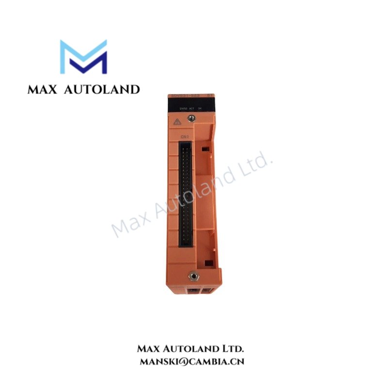
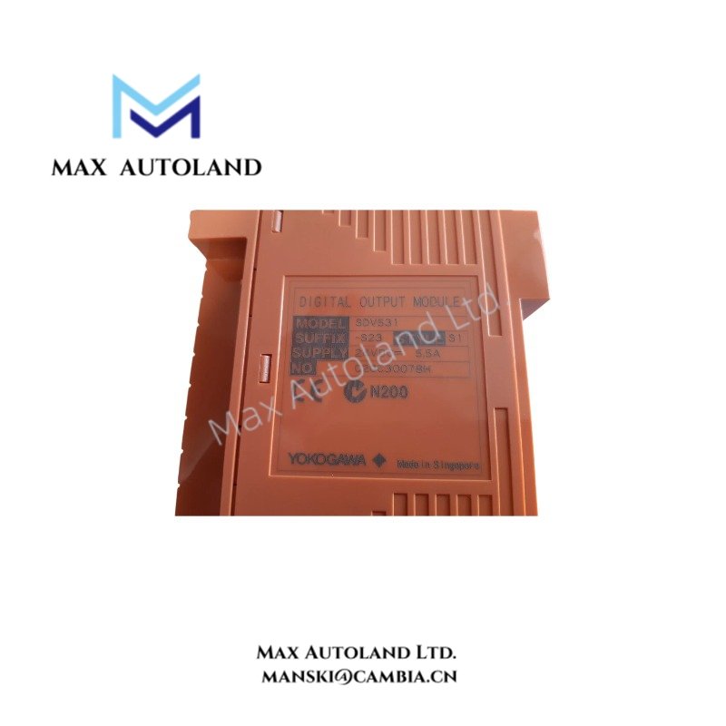
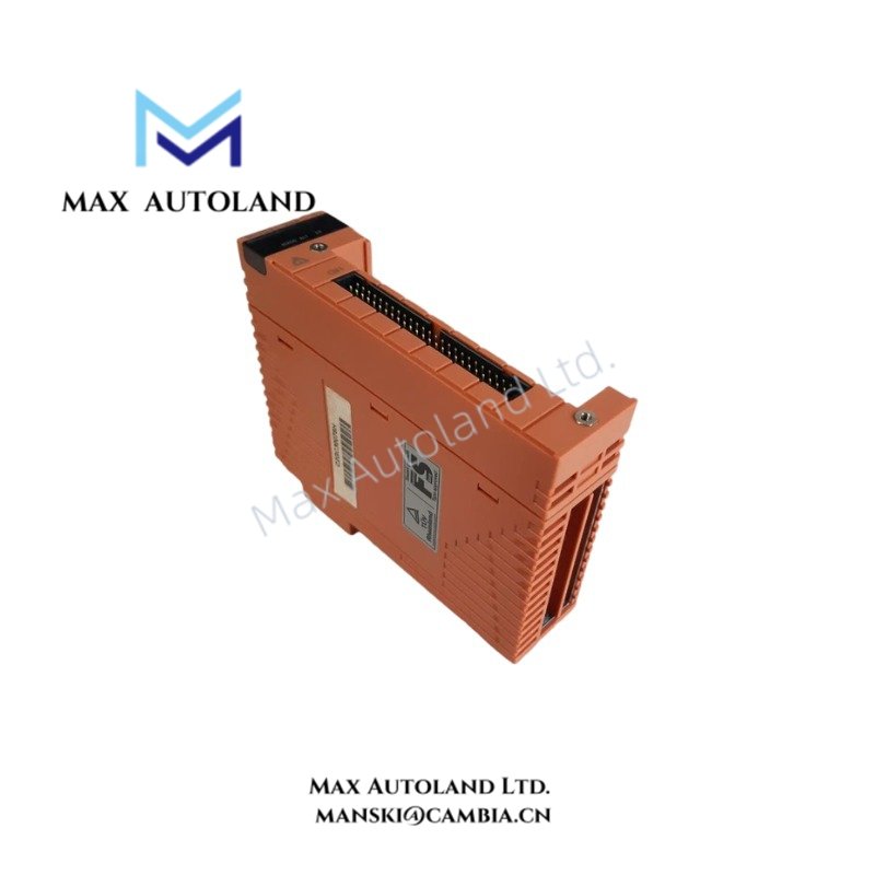
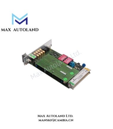
Overview
Suffix Breakdown & Model Matrix
| Model | Specification |
|---|---|
| SDV531 | Digital output module, 8 channels, module isolation |
| SDV531-S23 | Discontinued model |
| SDV531-S53 | Replacement model |
| -L | Long-distance type |
| -S | Standard type |
| 5 | Pressure clamp terminal block or MIL cable, without explosion protection |
| 6 | Signal cable interface adapter, without explosion protection |
| E | Pressure clamp terminal block or MIL cable, with explosion protection |
| F | Signal cable interface adapter, with explosion protection |
| 3 | ISA Standard G3 option and temperature range of -20 to 70 deg C |
Option codes
| Option Code | Specification |
|---|---|
| /B4S00 | STB4S-00 pressure clamp terminal block, without surge absorber |
| /B4S10 | STB4S-10 pressure clamp terminal block, with surge absorber |
| /B4D00 | STB4D-00 dual-redundant pressure clamp terminal block, without surge absorber |
| /B4D10 | STB4D-10 dual-redundant pressure clamp terminal block, with surge absorber |
| /PRP | Prevention pin for false insertion |
| /CCC01 | SCCC01 connector cover for MIL flat ribbon cable |
| /CCC02 | SCCC02 connector cover for discrete-wire MIL cable |
Note: Confirm the complete ordering code and applicable suffix combination against the manufacturer documentation before ordering.
Hardware Specifications
| Parameter | Specification |
|---|---|
| Model | SDV531-S53 |
| Base Model | SDV531 |
| Brand | Yokogawa |
| Product Type | Digital Output Module |
| System | ProSafe-RS |
| Number of Outputs | 8 channels |
| Isolation | Module isolation |
| Output Voltage | 24 VDC |
| Output Voltage Drop | 1 V maximum |
| Output Format | Current source |
| External Power Supply | 24 VDC, +20% / -10% |
| Minimum External Supply Capacity | 5 A |
| Maximum Load Current | 0.6 A per output line |
| Total Output Current | 4.8 A across all output lines |
| Minimum Load Current | 35 mA |
| Maximum Off-State Leakage Current | 1.6 mA |
| Load Resistance Range | 40 to 685 ohm |
| Output Response Time | 30 ms maximum |
| Withstand Voltage | 2 kVAC between output signal lines and system, under the specified test configuration |
| Current Consumption at 5 VDC | 280 mA maximum |
| Current Consumption at 24 VDC | 140 mA maximum |
| Weight | 0.28 kg with pressure clamp terminal block or MIL cable |
| Weight with Interface Adapter | 0.34 kg |
| Operating Temperature | -20 to 70 deg C for the specified ISA Standard G3 configuration |
Digital Output Electrical Characteristics and Isolation
The SDV531 provides eight current-source output channels with module-level isolation. Each output line supports a maximum load current of 0.6 A, with a combined maximum of 4.8 A across all eight output lines.
The external 24 VDC supply must meet the specified voltage tolerance and minimum current capacity. The maximum output voltage drop is 1 V. The specified load resistance range is 40 to 685 ohm, and the output response time is 30 ms maximum.
The module incorporates field wiring diagnostic functions. Dual-redundant configurations are supported with the applicable system configuration and terminal hardware. The supplied specifications do not define redundancy switchover time or individual channel-to-channel isolation.
Frequently Asked Questions
Q: What external power supply does the SDV531 require?
A: The module requires an external 24 VDC supply rated at +20% / -10%, with a minimum current capacity of 5 A.
Q: What is the maximum output current per channel?
A: The maximum load current is 0.6 A per output line, with a total maximum of 4.8 A across all eight output lines. Verify the field load current and resistance before connecting the load.
Q: Can the SDV531 operate in a dual-redundant configuration?
A: Yes. The supplied specifications state that the output module can be configured for dual redundancy. Confirm the applicable system configuration, terminal block type, and replacement compatibility before installation.
Field Installation Guidelines
- Verify the module model, suffix codes, terminal block, and cable interface against the system drawings.
- Confirm the external 24 VDC supply polarity, voltage tolerance, and available current capacity before connecting field wiring.
- Check each output load against the specified current and resistance limits.
- Verify the terminal connections and field wiring before energizing the module.
- Route output wiring separately from high-voltage power cables where practical to reduce electrical interference.
- Apply shield grounding according to the system grounding plan and the applicable Yokogawa installation manual.
- For redundant installations, verify the wiring arrangement and terminal hardware against the approved system design.
- Do not assume hot-swap capability or a specific redundancy switchover time without confirmation from the applicable hardware manual.
- For hazardous-area installations, confirm that the selected suffix and associated field wiring satisfy the applicable explosion-protection requirements.
YOKOGAWA Top Products
Customers Also Viewed




Reviews
There are no reviews yet.