
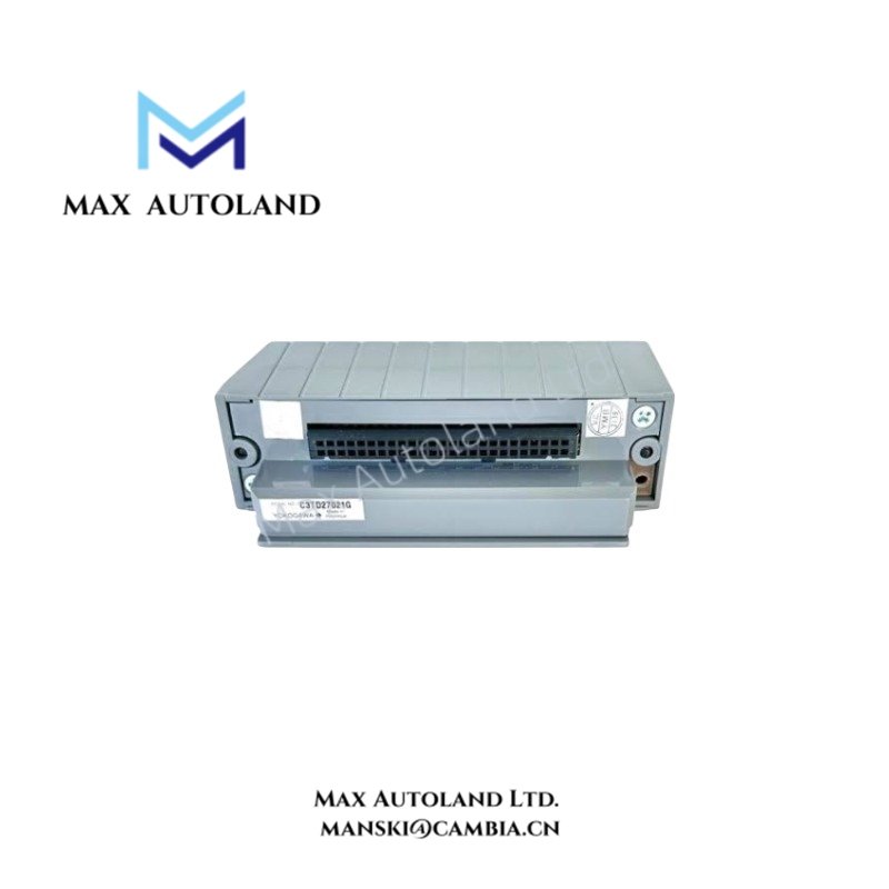
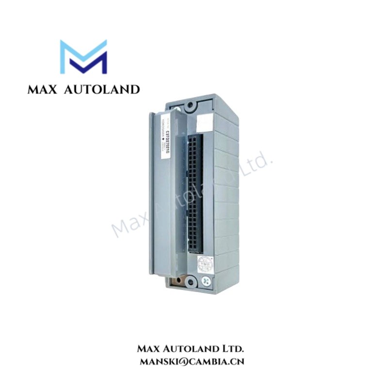
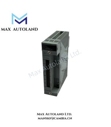
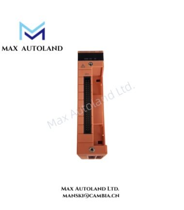
Overview
Hardware Specifications
| Parameter | Specification |
|---|---|
| Model | NFTB5S-00 |
| Brand | Yokogawa |
| Product Type | Pressure Clamp Terminal Block |
| Channel Capacity | 32 channels, as provided; confirm against the applicable hardware documentation |
| Wiring Connection | Pressure clamp terminal |
| Compatible System | Exact I/O module compatibility requires verification |
Field Wiring and Signal Interface
The NFTB5S-00 provides a termination point for field conductors. Correct operation depends on matching the terminal block to the supported I/O module and its field wiring arrangement.
- Connection compatibility: Verify the terminal block part number against the I/O module installation manual.
- Conductor termination: Use conductors and wire preparation methods permitted by the manufacturer’s terminal specifications.
- Electrical ratings: Confirm terminal voltage, current limits, and applicable signal type before connecting field circuits.
- Grounding and shielding: Follow the system wiring diagram for protective grounding and cable shield termination. Do not assume the terminal block provides galvanic isolation.
Frequently Asked Questions
Q: Is the NFTB5S-00 compatible with all Yokogawa I/O modules?
A: No universal compatibility is established by the supplied information. Verify the terminal block against the specific I/O module model and connection interface.
Q: Does the NFTB5S-00 provide electrical isolation between channels?
A: Channel-to-channel isolation is not confirmed. Check the manufacturer’s documentation for the applicable terminal block and associated I/O module.
Q: Can the terminal block be replaced while the control system is energized?
A: Hot replacement permission is not established by the supplied data. Follow the system maintenance procedure and isolate field power where required before disconnecting wiring.
Field Installation Guidelines
- Confirm the NFTB5S-00 part number and its compatibility with the target I/O module.
- De-energize affected circuits according to the site’s electrical safety procedures.
- Inspect terminal condition and prepare conductors according to the manufacturer’s wiring requirements.
- Route field signal cables separately from power conductors where required to reduce electrical interference.
- Terminate cable shields and protective earth connections according to the approved system wiring diagram.
- Verify conductor placement, polarity where applicable, and continuity before restoring power.
- Test the connected I/O channels against the control system’s commissioning procedure.
YOKOGAWA Top Products
Customers Also Viewed


Reviews
There are no reviews yet.