
Overview
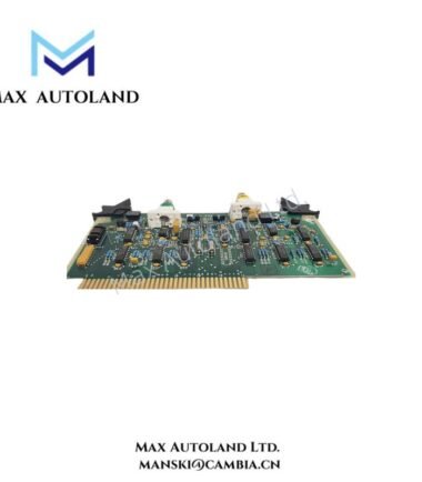
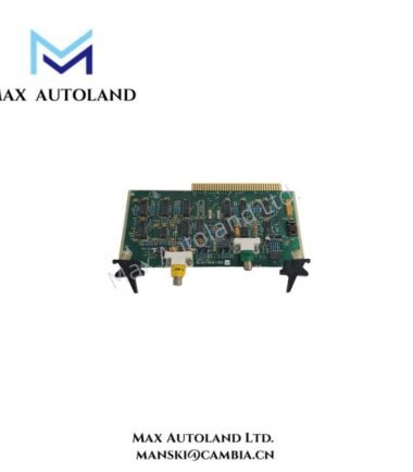
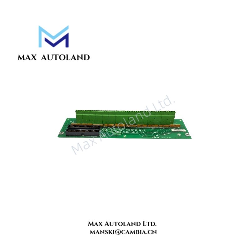
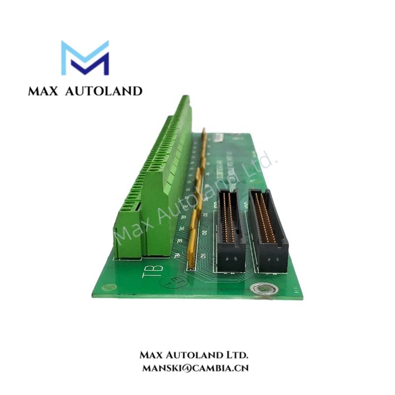
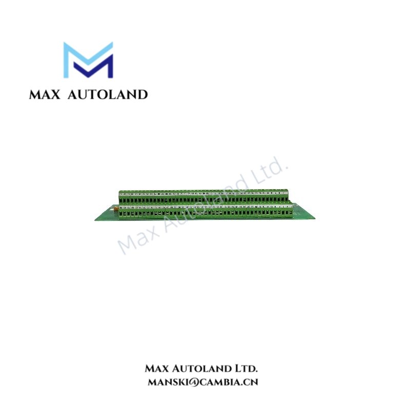
The GE DS200TBQFG1BBB, also identified by its base model DS200TBQFG1B, is described as a terminal board for electrical signal termination and field wiring connections. Its exact interface functions and compatibility with specific GE control platforms require confirmation from the applicable hardware documentation. The supplied information does not establish detailed electrical ratings or terminal assignments.
Hardware Specifications
| Parameter | Specification |
|---|---|
| Model | DS200TBQFG1BBB |
| Brand | General Electric (GE) |
| Series | Mark V |
| Product Type | Terminal Board |
| Primary Function | Field wiring termination and signal interfacing |
| Hardware Revision | G1BBB suffix |
| Tariff Code | 8537101190 |
Electrical Interface and Control System Compatibility
A terminal board provides physical connection points for conductors and may route signals between field wiring and other control hardware. However, the exact signal types, terminal assignments, electrical isolation, and interface architecture of the DS200TBQFG1BBB cannot be established from the supplied description alone.
For GE control system integration, verify the complete part number against the equipment bill of materials and the applicable hardware manual. Do not assume compatibility with Mark V or another platform based solely on the general product description.
Frequently Asked Questions (FAQ)
Q: Can the DS200TBQFG1BBB be replaced by another DS200TBQF variant?
A: Replacement compatibility has not been established. Compare the complete part number, board revision, connector layout, terminal assignments, and system configuration before selecting a substitute.
Q: What electrical signals does this terminal board support?
A: The supplied information does not identify supported signal types, voltage limits, current ratings, or channel assignments. Confirm these parameters using the corresponding GE schematic and hardware documentation.
Q: Can the DS200TBQFG1BBB be installed or removed while the system is energized?
A: Hot-swap capability is not documented in the supplied data. Follow the equipment-specific isolation procedure and verify the manufacturer’s installation instructions before removing or installing the board.
Field Installation Guidelines
- Verify identification: Check the complete DS200TBQFG1BBB part number and board markings against the equipment documentation.
- Isolate power: Apply the approved shutdown and electrical isolation procedure before handling the board unless the manufacturer explicitly authorizes energized work.
- Document wiring: Record existing conductor positions and terminal identifiers before disconnecting any field wiring.
- Inspect connections: Check connectors, terminal blocks, conductors, and the PCB for visible damage or contamination.
- Maintain wiring separation: Route signal conductors separately from power and high-noise switching circuits where the cabinet design requires separation.
- Check grounding and shielding: Follow the system grounding diagram and the specified shield termination method. Avoid introducing unintended ground paths.
- Verify before energization: Confirm wiring polarity, terminal assignments, connector engagement, and compatibility with the installed control hardware.