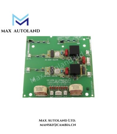
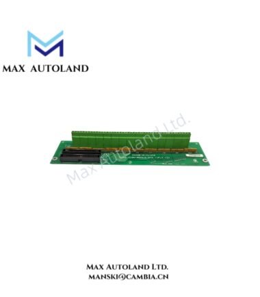
Overview
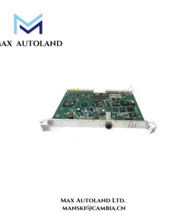
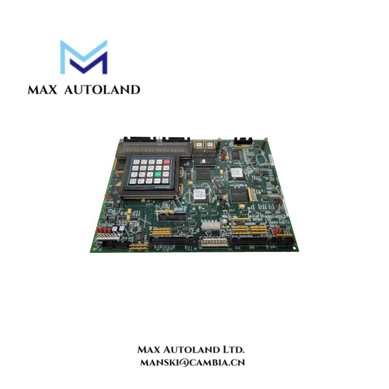
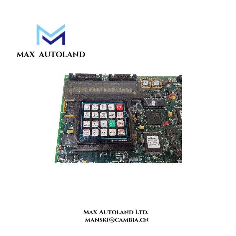
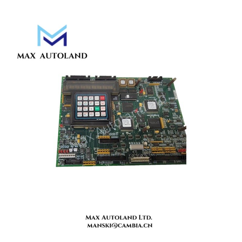
Configured for drive control data handling and LAN communication within GE drive control platforms, the GE DS200LDCCH1ANA (DS200LDCCH1ANA LAN Communications Board) provides board-level interfaces for control data processing and communication. The supplied specifications identify six flash PROM components at reference designators U7-U21, a 16-character digital display, a KPPL connector, and support for analog signal conversion and voltage-controlled oscillator (VCO) inputs. The exact relationship between these functions and the board’s LAN interface requires confirmation against the applicable GE hardware manual.
Hardware Specifications
| Parameter | Specification |
|---|---|
| Model | DS200LDCCH1ANA |
| Brand | General Electric (GE) |
| Series | Drive Control |
| Product Type | LAN Communications Board |
| Origin | United States of America (USA) |
| Operating Temp | 0 to 60 deg C (supplied specification) |
| Configuration Storage | Six flash PROM components reported |
| Display | 16-character digital display, as described in the supplied data |
| Interface Connector | KPPL connector, as described in the supplied data |
| Signal Functions | Analog-to-digital (A/D) and digital-to-analog (D/A) conversion; VCO input support reported |
| Additional Connector | Stab connector reported |
GE Drive Control Hardware and Firmware Compatibility
The DS200LDCCH1ANA belongs to the GE Drive Control product category. Its reported flash PROM components store board configuration or program data, while the display provides local status information. However, the exact memory allocation, firmware revision requirements, and communication protocol specifications are not established by the supplied information.
When integrating this board into a drive system, verify the complete part number, board revision, connector layout, and firmware requirements against the applicable GE documentation. Do not assume that specifications for the DS200LDCCH1ANA-W01 apply to the DS200LDCCH1ANA without confirmation.
Frequently Asked Questions
Q: Does the DS200LDCCH1ANA support hot swapping?
A: The supplied information does not confirm hot-swap capability. Isolate the applicable power sources and follow the drive manufacturer’s shutdown and replacement procedures before removing the board.
Q: What operating temperature range does the board support?
A: The supplied specification states 0 to 60 deg C. Confirm the permitted ambient temperature and any cooling requirements in the hardware manual for the installed revision.
Q: Which firmware or configuration data does the board require?
A: The supplied description reports six flash PROM components. However, it does not identify the firmware version or configuration files required for a specific drive. Check the system configuration and board revision before replacement or firmware service.
Field Installation Guidelines
- Verify identification: Compare the board label, complete part number, revision, and connector arrangement with the installed hardware documentation.
- Isolate power: Follow the drive manufacturer’s shutdown procedure and verify that hazardous electrical energy has been removed before handling the board.
- Apply ESD precautions: Use an approved antistatic wrist strap and suitable ESD-safe handling practices.
- Inspect connectors: Check the board edge contacts, KPPL connector, and any auxiliary connectors for contamination, damage, or loose connections.
- Route cables correctly: Keep communication and low-level signal wiring separated from motor leads and other high-noise conductors where the system design permits. Follow the manufacturer’s shielding and grounding instructions.
- Verify configuration: Confirm firmware compatibility, board addressing, and drive configuration requirements before energizing the equipment.
- Perform functional checks: After installation, inspect diagnostic indications and verify communication and drive operation using the approved commissioning procedure.