Overview
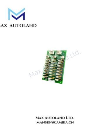
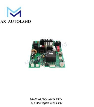
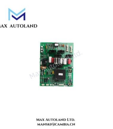
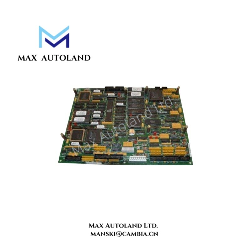
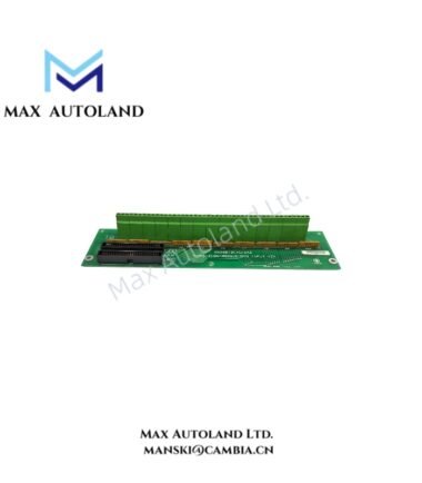
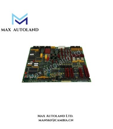
The GE DS200LRPBG1AAA, also identified by the base model DS200LRPBG1AAA, is a Resolver Board specified for the GE Mark V control system. It processes resolver-related signals for rotor position feedback and associated control functions. The supplied documentation identifies its function but does not specify its electrical input range, conversion resolution, or interface protocol.
Hardware Specifications
| Parameter | Specification |
|---|---|
| Model | DS200LRPBG1AAA |
| Brand | General Electric (GE) |
| Series | Mark V |
| Product Type | Resolver Board |
| Origin | United States of America (USA) |
| Primary Function | Resolver signal processing |
| Feedback Type | Rotor position feedback |
| Signal Conversion | Analog-to-digital processing described in the supplied documentation; implementation details require verification |
| System Compatibility | GE Mark V, subject to hardware revision and system configuration |
| Availability | In Stock, as supplied |
Resolver Signal Processing and Control Interface
The DS200LRPBG1AAA is identified as a resolver interface board for rotor position feedback. A resolver produces electrical signals associated with shaft position. The control system uses these signals to determine rotor position and support related control calculations.
The supplied description also identifies connectors, signal-processing circuitry, and diagnostic indicators as board features. However, the exact connector assignments, LED meanings, channel count, and signal conditioning specifications require confirmation from the applicable GE documentation.
For system integration, engineers should verify the resolver excitation requirements, signal input characteristics, feedback scaling, and interface compatibility before connecting the board to an operating control system.
Frequently Asked Questions (FAQ)
Q: What is the primary function of the GE DS200LRPBG1AAA?
A: It is identified as a Resolver Board for the GE Mark V control system. Its stated function relates to resolver signal processing and rotor position feedback.
Q: Can the DS200LRPBG1AAA be replaced without checking the existing board configuration?
A: No. Verify the complete part number, board revision, connector arrangement, system configuration, and applicable GE replacement instructions before installation.
Q: What electrical parameters must be checked before connecting a resolver?
A: Confirm resolver excitation voltage and frequency, signal amplitude, input wiring, grounding, shielding, and the supported feedback interface against the applicable technical documentation. The supplied information does not establish numerical limits for these parameters.
Field Installation Guidelines
- Verify identification: Check the complete DS200LRPBG1AAA part number and the installed board revision against the system documentation.
- Isolate power: Follow the equipment manufacturer’s shutdown and electrical isolation procedures before removing or installing the board.
- Inspect connections: Check connectors, terminals, and mating interfaces for damage, contamination, or loose contacts.
- Check resolver wiring: Confirm signal assignments, excitation connections, cable routing, and polarity against the approved wiring diagram.
- Maintain signal integrity: Route resolver signal cables away from high-current conductors and switching power circuits where practical. Apply the specified shielding and grounding arrangement.
- Verify configuration: Confirm that the replacement board matches the required hardware revision and system configuration before energizing the equipment.
- Perform functional checks: After installation, verify feedback status and rotor position readings using approved commissioning procedures. Investigate diagnostic indications before returning the system to service.