
Overview
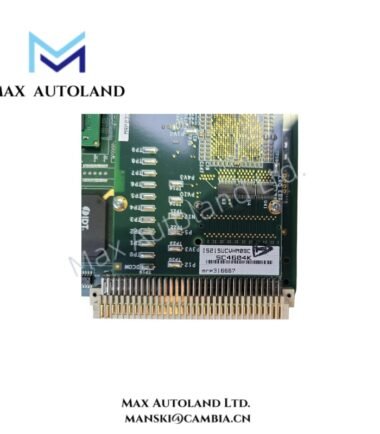
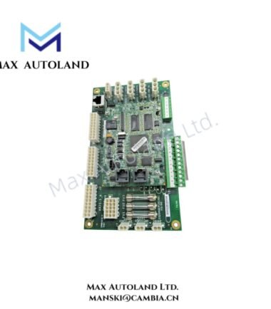
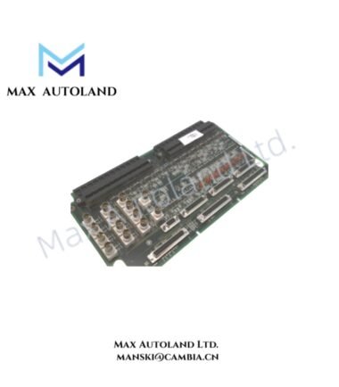
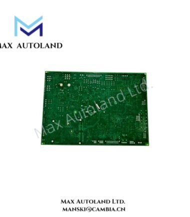
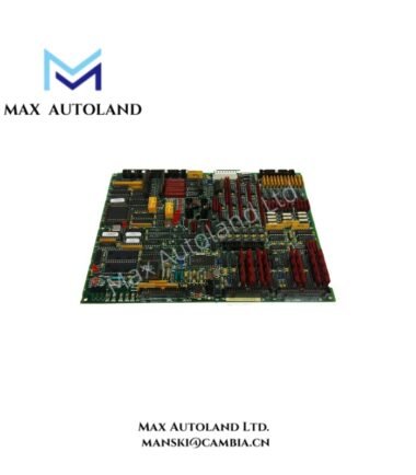
The GE DS200TCQCG1BHF, also cataloged as the DS200TCQCG1BHF Overflow Card, is an EX2000 RST printed circuit board associated with the GE Mark V control system. It provides excitation for LVDT and LVDR circuits. The board includes relay components, integrated circuits, jumper switches, test points, and multiple pin connectors. Verify the board revision and installed configuration before replacement.
Hardware Specifications
| Parameter | Specification |
|---|---|
| Model | DS200TCQCG1BHF |
| Brand | General Electric (GE) |
| Series | Mark V / EX2000 |
| Product Type | Overflow Card |
| Function | LVDT and LVDR excitation |
| Board Configuration | RST printed circuit board |
| Vertical Pin Cable Connectors | 11 |
| Male Vertical Pin Header Connectors | 5 |
| Vertical Female Plug | 1 |
| Relay Components | 6 |
| Jumper Switches | 37 |
| Integrated Circuits | Approximately 40 |
GE Mark V Excitation Circuit Characteristics
The DS200TCQCG1BHF supports excitation for LVDT and LVDR circuits within the EX2000 control configuration. Its board-level components include relay circuits, integrated circuits, and jumper switches.
The board contains test points for electrical inspection. Technicians should verify the applicable schematic, jumper positions, connector assignments, and circuit references before testing or replacing the assembly. The available information does not establish specific excitation voltage levels, signal ranges, or jumper functions.
Frequently Asked Questions
Q: What is the primary function of the DS200TCQCG1BHF?
A: The DS200TCQCG1BHF is an EX2000 RST overflow card associated with the GE Mark V control system. The supplied description identifies LVDT and LVDR excitation as its function.
Q: How many connectors does the DS200TCQCG1BHF have?
A: The documented configuration includes 11 vertical pin cable connectors, 5 male vertical pin header connectors, and 1 vertical female plug.
Q: Can the DS200TCQCG1BHF be replaced without checking its jumper configuration?
A: No. Verify the installed jumper positions, connector assignments, board revision, and applicable system documentation before replacement. The available data does not specify hot-swap capability or universal interchangeability.
Field Installation Guidelines
- Isolate the relevant control-system power sources and follow the site’s lockout and verification procedures before removing the board.
- Record connector positions, jumper settings, and board identification markings before disconnection.
- Inspect connectors, pin contacts, component surfaces, and the PCB for physical damage or contamination.
- Use appropriate electrostatic discharge precautions when handling the assembly.
- Confirm the replacement board’s full part number, revision, and configuration against the installed hardware and system documentation.
- Restore wiring and jumpers according to the applicable GE drawings. Do not infer electrical settings from physical similarity alone.
- Complete the required continuity, excitation-circuit, and system functional checks before returning the control system to service.