


Overview
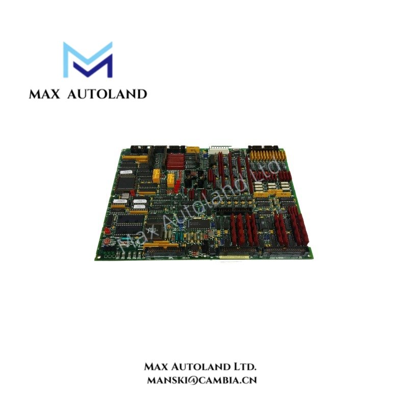
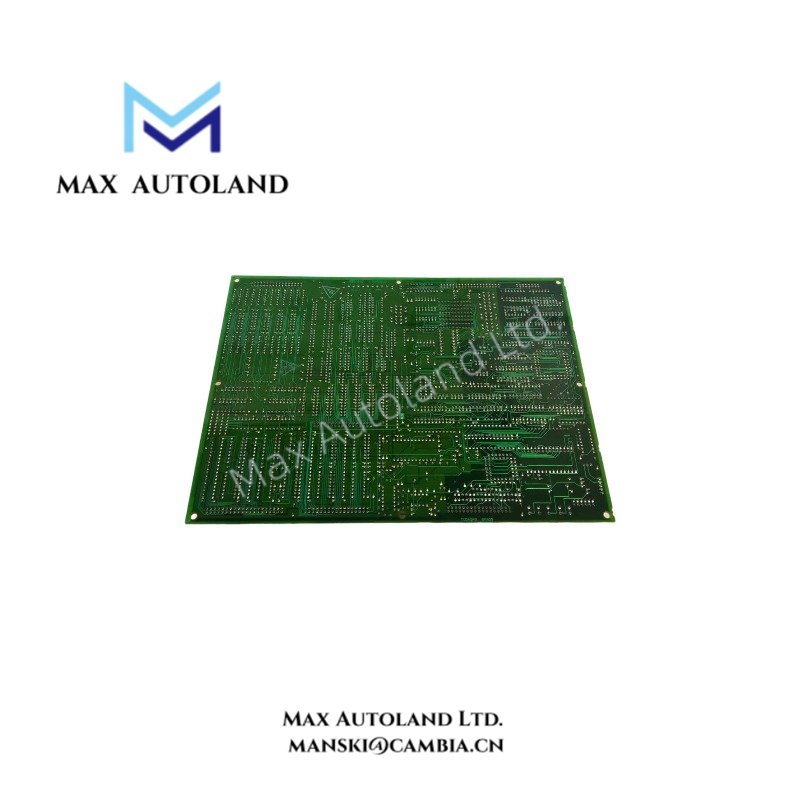
The GE DS200TCQAG1BFD, also associated in the supplied record with DS215TCQAG1BZZ01A, is identified as an RST analog interface board for the Mark V turbine control system. The board record describes an analog I/O interface, but the exact assembly relationship, signal ranges, and electrical characteristics remain unverified. Confirm the installed hardware markings and configuration before selecting a replacement.
Hardware Specifications
| Parameter | Specification |
|---|---|
| Model | DS200TCQAG1BFD |
| Associated Model | DS215TCQAG1BZZ01A |
| Brand | General Electric (GE) |
| Product Type | RST Analog Interface Board |
| Series | Mark V |
| Origin | USA |
| 34-Pin Connectors | 4; manufacturer verification pending |
| 40-Pin Connectors | 2; manufacturer verification pending |
| Configuration Jumpers | 6; manufacturer verification pending |
Mark V Analog Interface and Configuration Verification
The board is identified as an analog interface component within the GE Mark V control platform. However, the supplied record does not establish its supported input or output ranges, channel assignments, isolation characteristics, or backplane electrical requirements.
Before installation, compare the board revision, connector layout, jumper positions, and system configuration with the applicable manufacturer documentation. Backplane communication compatibility and firmware requirements also require confirmation against the installed Mark V hardware.
Frequently Asked Questions (FAQ)
Q: Are DS200TCQAG1BFD and DS215TCQAG1BZZ01A interchangeable?
A: The supplied record associates these identifiers, but it does not establish a manufacturer-confirmed replacement relationship. Verify the assembly designation, revision, and system compatibility before substitution.
Q: Are the connector and jumper counts confirmed specifications?
A: No. The record lists four 34-pin connectors, two 40-pin connectors, and six configuration jumpers. These counts require physical inspection or manufacturer documentation.
Q: What analog signal ranges does this board support?
A: The available information does not confirm the supported signal ranges. Consult the applicable Mark V hardware documentation and verify the installed configuration before connecting field signals.
Field Installation Guidelines
- Isolate the relevant equipment and follow the site’s approved electrical safety and lockout procedures before removing the board.
- Record the complete board markings, revision identifiers, connector positions, and existing jumper configuration.
- Compare the replacement hardware against the original assembly and the applicable GE documentation.
- Inspect connectors and mating interfaces for damage, contamination, or loose contacts before installation.
- Maintain the original wiring identification and route analog signal cables separately from high-noise power conductors where practical.
- Verify shield termination and grounding against the system wiring drawings and site grounding requirements.
- Confirm signal assignments, electrical compatibility, and control-system configuration before restoring power.
- Perform the prescribed system diagnostics and functional checks before returning the equipment to service.


