Overview
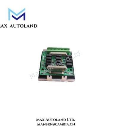
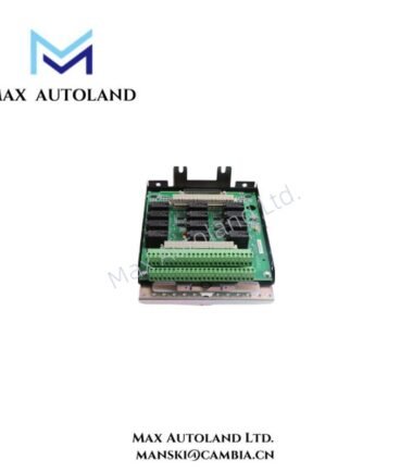
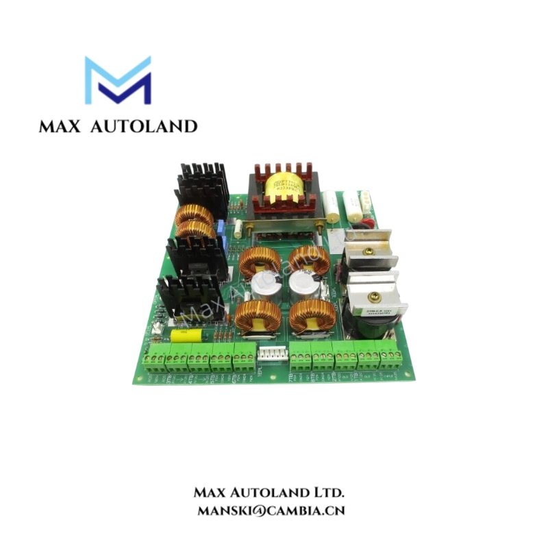
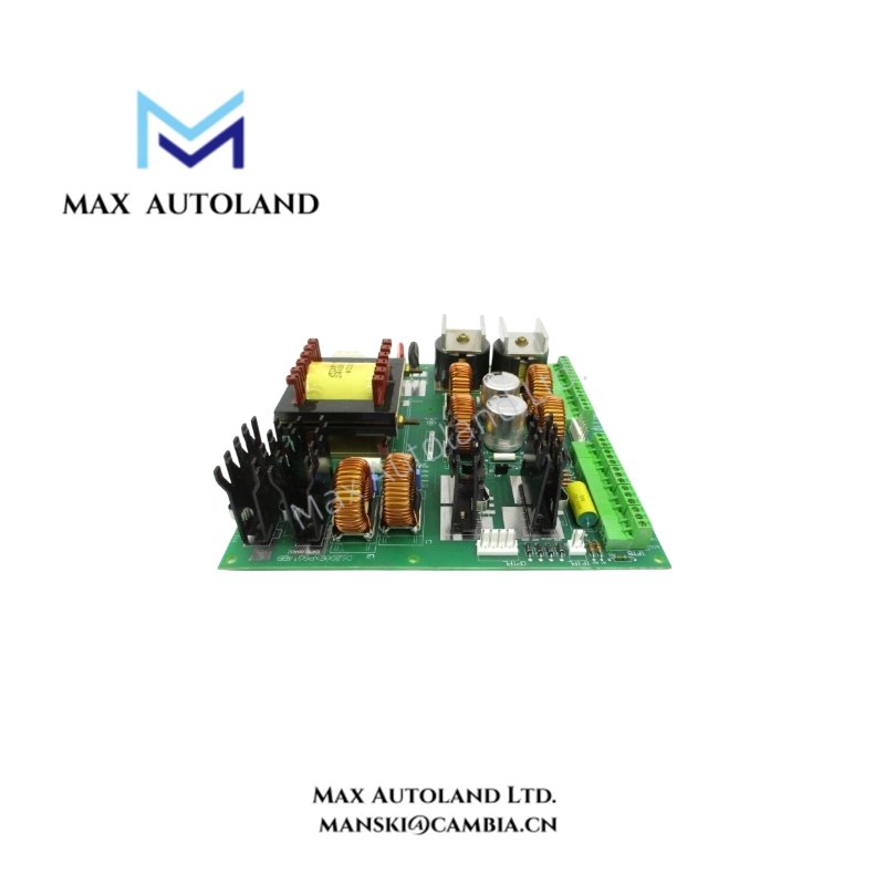
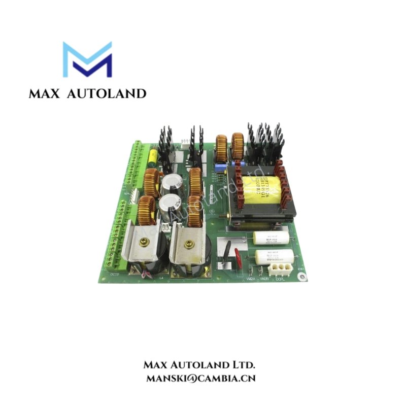
The DS200EXPSG1ABB is a Power Supply Board manufactured by General Electric (GE) for the EX2000 excitation system. It supports AC and DC input power measurement and provides current-limiting protection when powered by a station battery. Furthermore, its jumper configuration supports the grounding arrangement of the power supply circuit.
Technical Specifications
| Parameter | Specification |
|---|---|
| Model | DS200EXPSG1ABB |
| Brand | General Electric (GE) |
| Series | EX2000 |
| Product Type | Power Supply Board |
| Operating Temperature | 0 to 60 deg C (32 to 149 deg F) |
| Country of Origin | United States (USA) |
| Availability | In Stock |
Functions and Features
AC and DC Power Measurement
The DS200EXPSG1ABB provides signals for measuring AC and DC input power within the EX2000 excitation system. These signals support power monitoring and regulation, allowing the system to track its input power conditions.
Station Battery Current Limiting
When the board operates with a station battery supply, its current-limiting function restricts excessive current flow. This protection helps prevent abnormal current conditions from affecting the board and connected power supply components.
Power Supply Regulation
The board forms part of the EX2000 power supply assembly. It supports power distribution and regulation within the excitation system. In addition, its grounding configuration helps establish the required electrical reference for the power supply circuit.
Jumper Configuration
The DS200EXPSG1ABB uses jumper JP1 to connect the center tap of transformer T1’s secondary winding to ground. This connection determines the grounding arrangement of the transformer secondary circuit.
When replacing the board, retain the original JP1 position. Therefore, record the jumper position on the existing board before removal and reproduce that setting on the replacement board.
For jumper adjustment, the supplied instructions specify the following conditions:
- Remove the black and white wires from CPSP TB1 and PTB2 terminal boards.
- Disconnect ACPL before making adjustments.
- Position JP1 according to the system’s required grounding configuration.
Board Replacement Procedure
The following procedure summarizes the supplied replacement instructions for the EXPS power supply assembly.
- Isolate the power supply. Shut down the power supply and verify zero electrical potential at all connections before starting work.
- Disconnect the assembly. Remove the required connections from FTB, 1TB through 8TB, DCTB, VM2A and VM2B. Keep ACPL installed during assembly removal.
- Remove the assembly. Unscrew the four mounting screws and carefully lift the power supply assembly out of the cabinet.
- Prepare the work area. Move the assembly to a clean, static-free workbench. Remove the four screws securing the plastic protective cover.
- Disconnect the EXPS board. Unplug the DCPL, 3GDPL and 4GDPL connectors from the board.
- Replace the board. Remove the existing EXPS board and install the DS200EXPSG1ABB replacement. Set JP1 to exactly the same position as on the original board.
- Reassemble the unit. Reconnect the removed connectors and secure the plastic protective cover with its four screws.
- Reinstall the assembly. Return the power supply assembly to the cabinet and reconnect all cables according to their original labels. Check that each connector is fully seated.
Frequently Asked Questions
Q: What is the function of the JP1 jumper on the DS200EXPSG1ABB?
A: JP1 connects the center tap of transformer T1’s secondary winding to ground. Its position determines the grounding configuration, so retain the original setting when replacing the board.
Q: Does the DS200EXPSG1ABB provide current-limiting protection?
A: Yes. The board provides current-limiting protection when powered by a station battery, helping restrict excessive current flow in the power supply circuit.
Q: What should be checked when replacing the DS200EXPSG1ABB?
A: Record the original JP1 position before removing the board. Furthermore, label and reconnect all cables correctly, and ensure that DCPL, 3GDPL and 4GDPL are properly connected during reassembly. Isolate the power supply and verify zero potential before beginning work.