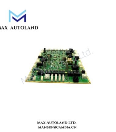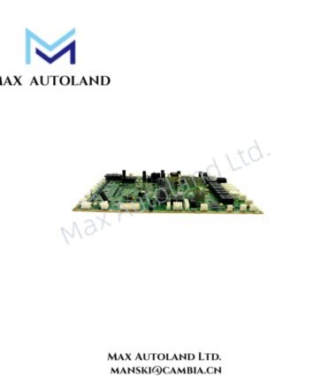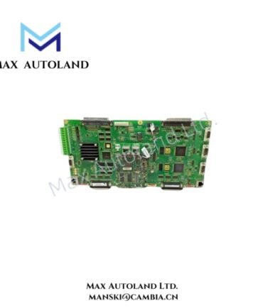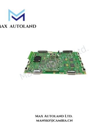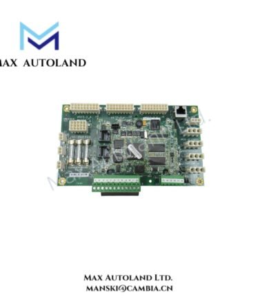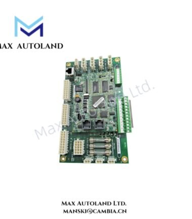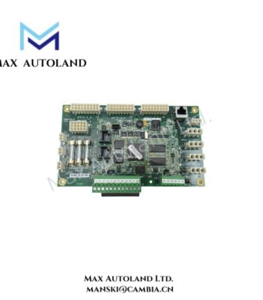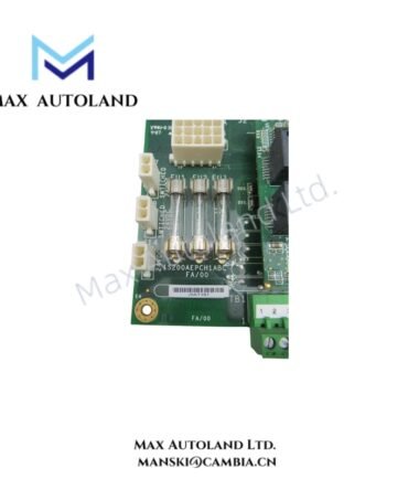

Overview
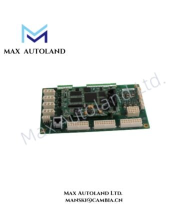
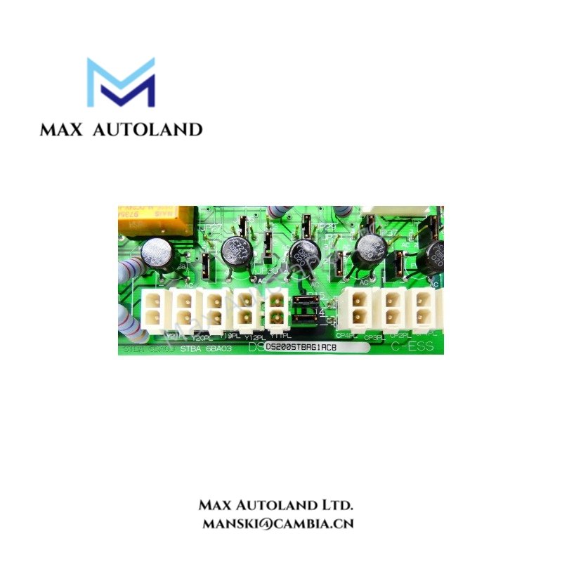
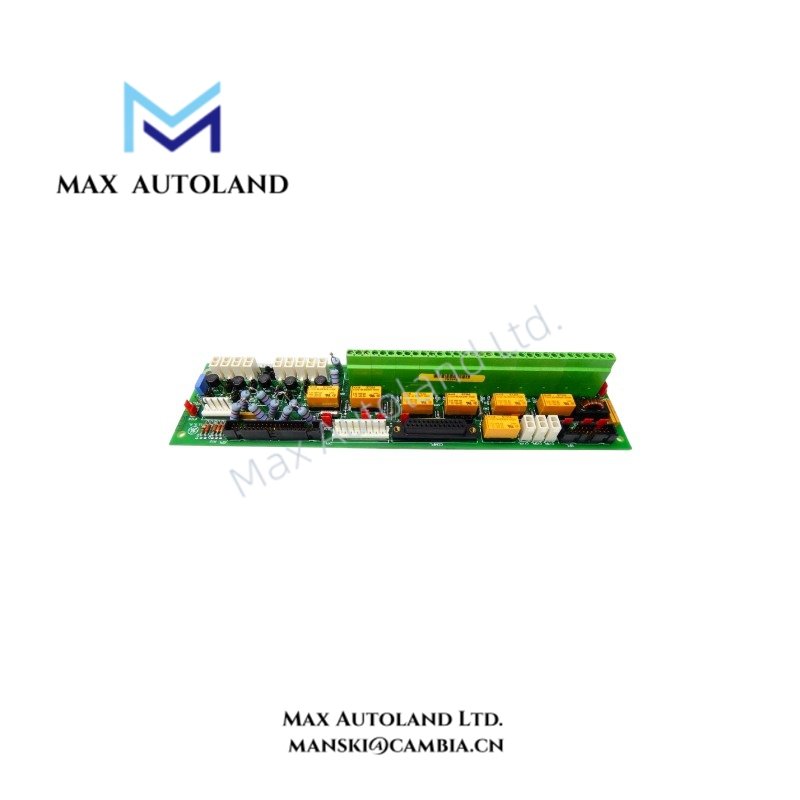
The GE DS200STBAG1ACB, also cataloged as the DS200STBAG1A Basic Drive Terminal Board, provides terminal connections for signal wiring within GE Mark V drive control systems. The board has 66 screw terminals arranged in two rows and supports signal-level connections, RS-232C communication, and 5 V or 15 V A-quad-B encoder interfaces, according to the supplied specifications.
Hardware Specifications
| Parameter | Specification |
|---|---|
| Model | DS200STBAG1ACB |
| Base Model | DS200STBAG1A |
| Brand | GE |
| Product Type | Basic Drive Terminal Board |
| Product Series | Mark V / DS200 |
| Board Designation | STBA |
| Origin | USA |
| Terminal Count | 66 screw terminals |
| Terminal Arrangement | 2 rows |
| Regulated Supply Voltages | +5 VDC, +/-15 VDC |
| Unregulated Supply Voltages | +/-24 VDC, 120 VAC |
| Communication Interface | RS-232C |
| Encoder Compatibility | 5 V or 15 V A-quad-B encoders |
| Configuration Tool | ST2000 Toolkit |
| Manual Reference | GEI-100177 |
| Tariff Code | 8537101190 |
Drive Signal Interfaces and Electrical Compatibility
The DS200STBAG1ACB provides screw-terminal connection points for drive control signals. Its documented electrical interfaces include regulated and unregulated supply voltages, an RS-232C serial interface, and A-quad-B encoder compatibility.
The specified supply voltages describe supported voltage categories; they do not establish the current capacity or terminal-by-terminal allocation. Confirm the wiring assignments against the applicable GEI-100177 documentation before connecting field devices.
For GE drive maintenance, verify board revision compatibility, signal assignments, and configuration software requirements against the installed Mark V system documentation. Do not infer firmware compatibility solely from the DS200 model prefix.
Frequently Asked Questions (FAQ)
Q: How many terminal connections does the DS200STBAG1ACB provide?
A: The supplied specifications identify 66 screw terminals arranged in two rows.
Q: Which encoder types are supported?
A: The supplied specifications list 5 V and 15 V A-quad-B encoders. Verify the encoder electrical requirements and terminal assignments against the applicable system documentation.
Q: Can the board be replaced while the drive is energized?
A: Hot-swap capability is not established by the supplied information. Isolate the equipment and follow the approved GE maintenance procedure before removing or installing the board.
Field Installation Guidelines
- Verify the complete board number, including the ACB suffix, against the equipment bill of materials and approved replacement documentation.
- Isolate power and apply the site’s lockout/tagout procedure before handling the board.
- Record existing terminal connections and wire labels before disconnecting conductors.
- Check terminal assignments, voltage levels, and encoder signal compatibility against the applicable GEI-100177 documentation.
- Route signal and communication wiring separately from high-noise power conductors where the cabinet design permits.
- Apply shielding and grounding according to the system wiring diagrams. Avoid introducing unintended ground paths.
- Inspect terminal connections, connectors, and the board for physical damage before energizing the equipment.
- After installation, verify signal continuity, communication operation, and drive diagnostics in accordance with the approved commissioning procedure.