
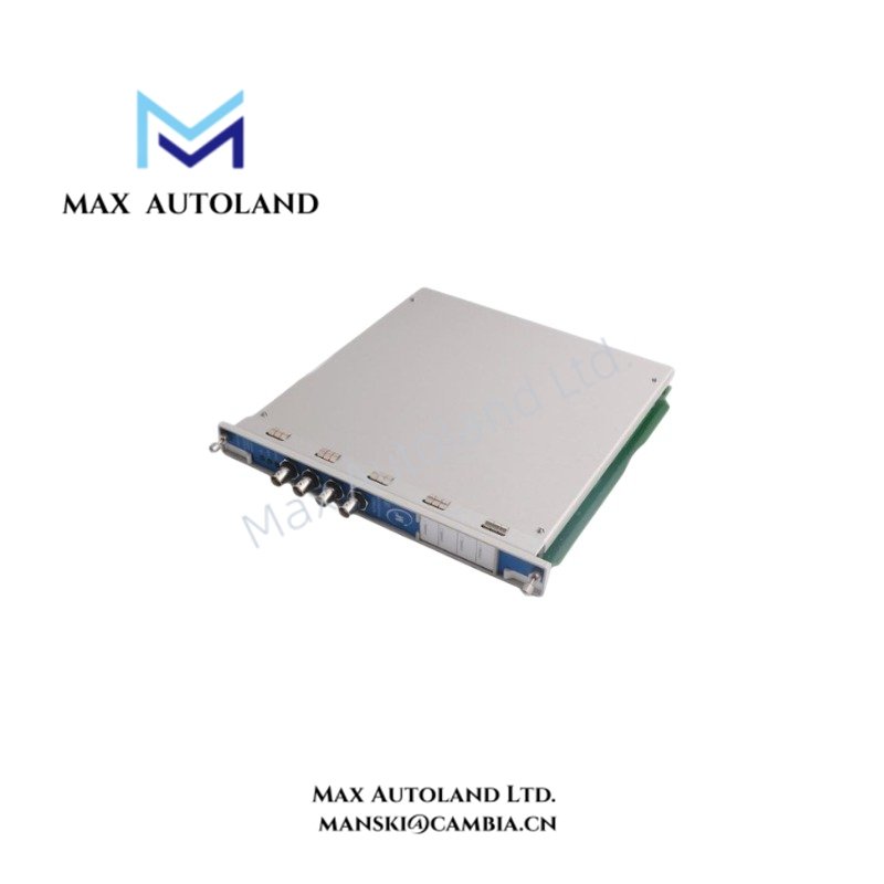
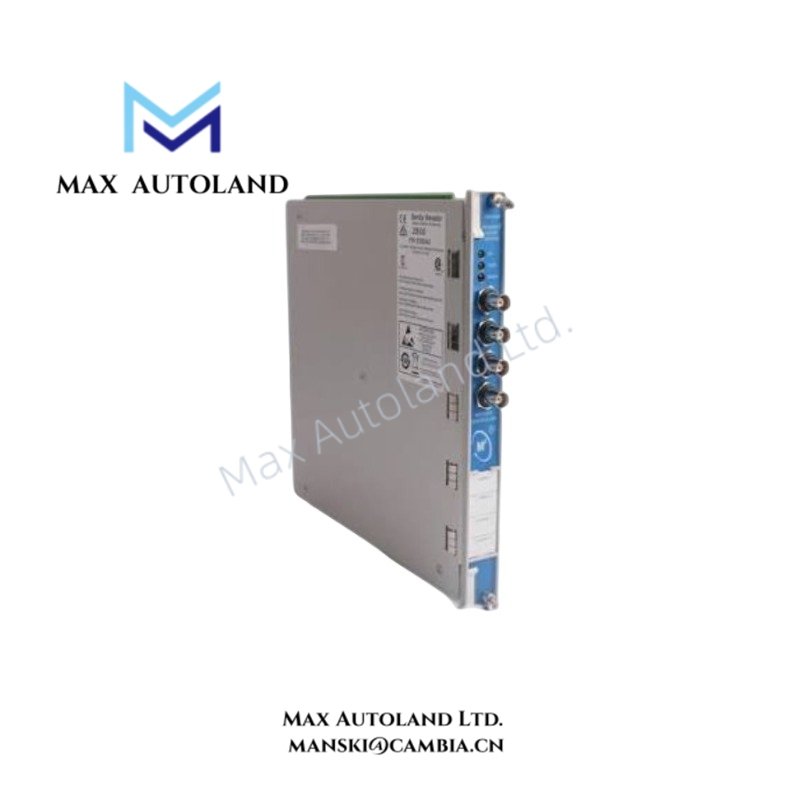
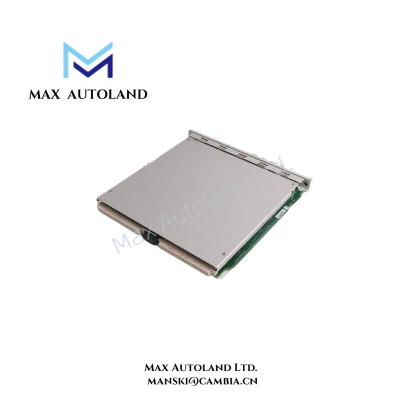

Overview
Hardware Specifications
| Parameter | Specification |
|---|---|
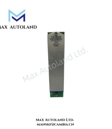
| Model | 3500/46M 176449-06 |
| Brand | Bently Nevada |
| Product Type | Hydro Monitor |
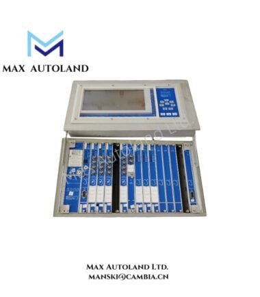
| Series | 3500 Machinery Protection System |
| Monitoring Channels | Four |
| Supported Measurements | Hydro vibration, air gap, thrust, dynamic pressure and SEW with matching I/O |
| Mode-Specific Alarm Sets | Up to eight with supported multimode arrangement |
| Prox/Accel Input Impedance | 10 kohm with Prox/Velom I/O |
| Velomitor Input Impedance | 3.5 Mohm with Prox/Velom I/O |
| Buffered Output Impedance | 550 ohm |
| Recorder Outputs | 4-20 mA per channel |
| Recorder Load | 0-600 ohm |
| Recorder Update | 100 ms or less |
| Typical Power Consumption | 7.7 W |
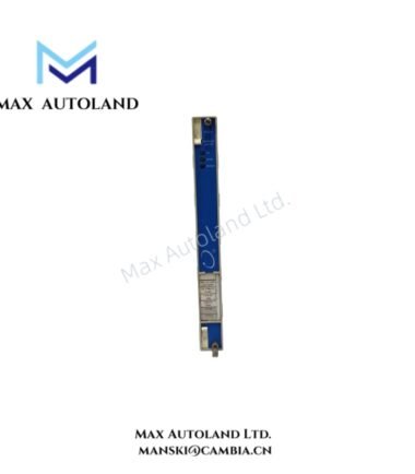
| Front Status Indication | OK, TX/RX and Bypass |
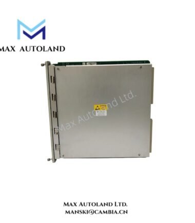
| Rack Allocation | One full-height front slot |
Hydro Measurement and Signal Processing
The 3500/46M accepts measurement configurations through the selected rear I/O arrangement. Prox/Accel and Velomitor signal interfaces have different input impedance characteristics, so the rear I/O must match the connected sensor system.
The monitor can process hydro vibration, air gap, thrust, dynamic pressure and SEW measurements when the corresponding I/O and sensor configuration are installed. Mode-specific alarm sets can support changing hydro turbine operating conditions. The recorder interface provides one 4-20 mA output per configured channel with a specified 0-600 ohm recorder load.
For proximity-based measurements, the sensor interface requires correct probe scaling and electrical validation. Where eddy-current proximity probes are used, the installed probe system should be checked for the specified gap voltage and signal range before commissioning. A nominal -10 VDC target is commonly used when validating Bently Nevada proximity probe installation, but the exact acceptance range must follow the applicable sensor and I/O documentation.
Frequently Asked Questions
Q: Can the 3500/46M 176449-06 use any 3500 rear I/O module?
A: No. The rear I/O must match the selected hydro measurement and connected sensor type. Confirm the I/O configuration before installation.
Q: What is the specified power consumption of the monitor?
A: Typical power consumption is 7.7 W. The actual rack power load also depends on the installed I/O configuration.
Q: Does Hydro Velocity provide an automatic machinery protection function?
A: No. The supplied data specifies that the Hydro Velocity function is not intended for automated machinery protection.
Field Installation Guidelines
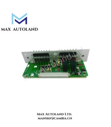
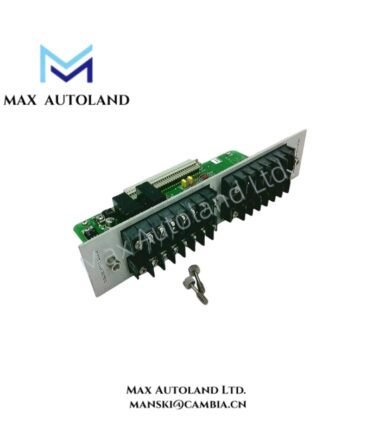
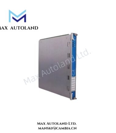
Install the 3500/46M 176449-06 in the designated full-height front slot of the 3500 rack. Confirm that the rack backplane and selected rear I/O arrangement correspond to the monitor configuration before connecting field wiring.
Match each sensor circuit to its specified I/O type. Keep sensor wiring separated from high-current power conductors and switching circuits where practical. Use the specified cable shielding and termination method for the installed Bently Nevada sensor system.
For proximity probe applications, verify probe polarity, excitation, gap voltage and signal scaling before placing the channel into service. Do not substitute a different sensor interface without confirming electrical compatibility.
Confirm the recorder output load before connecting external recording equipment. Each configured recorder output is specified for a 0-600 ohm load.
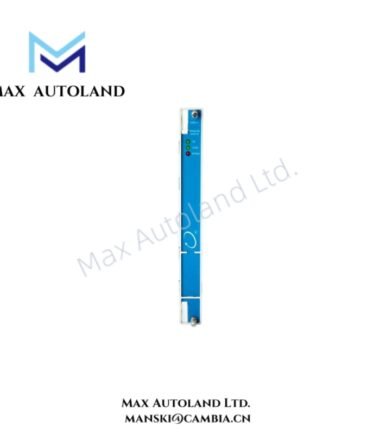
After installation, check the front OK, TX/RX and Bypass indications. Verify channel measurements against the configured sensor type and operating mode before enabling any downstream monitoring or alarm functions.


Reviews
There are no reviews yet.