
Overview
Hardware Specifications
| Parameter | Specification |
|---|---|
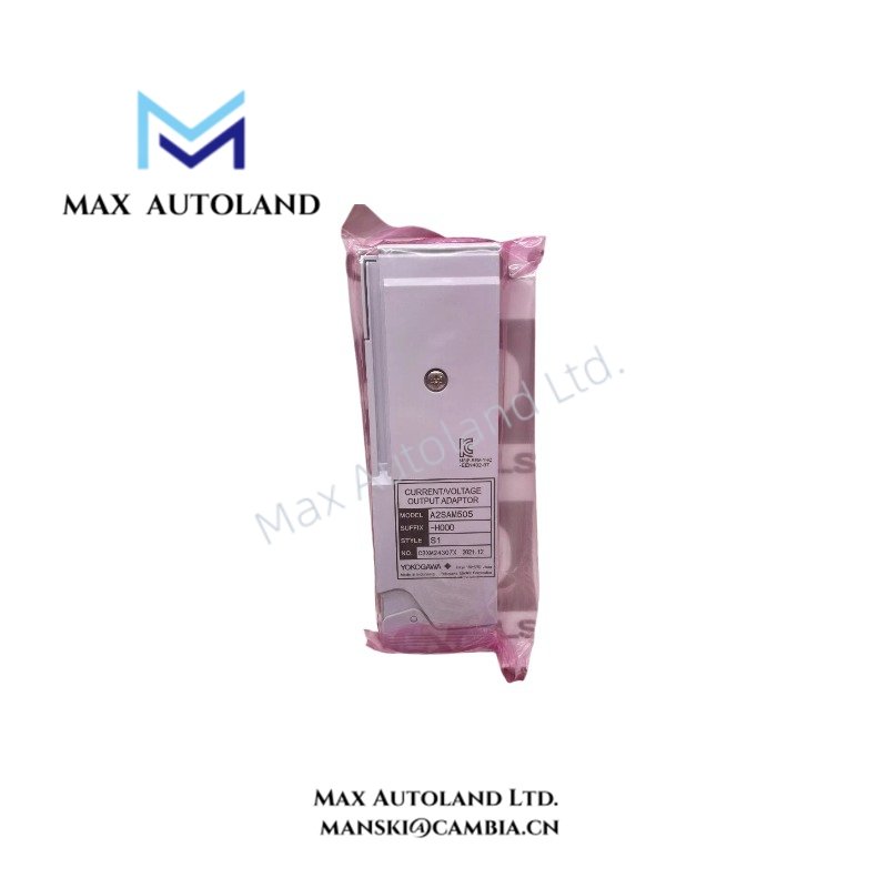
| Model | A2SAM505-H000 S1 |
| Base Model | A2SAM505 |
| Brand | Yokogawa |
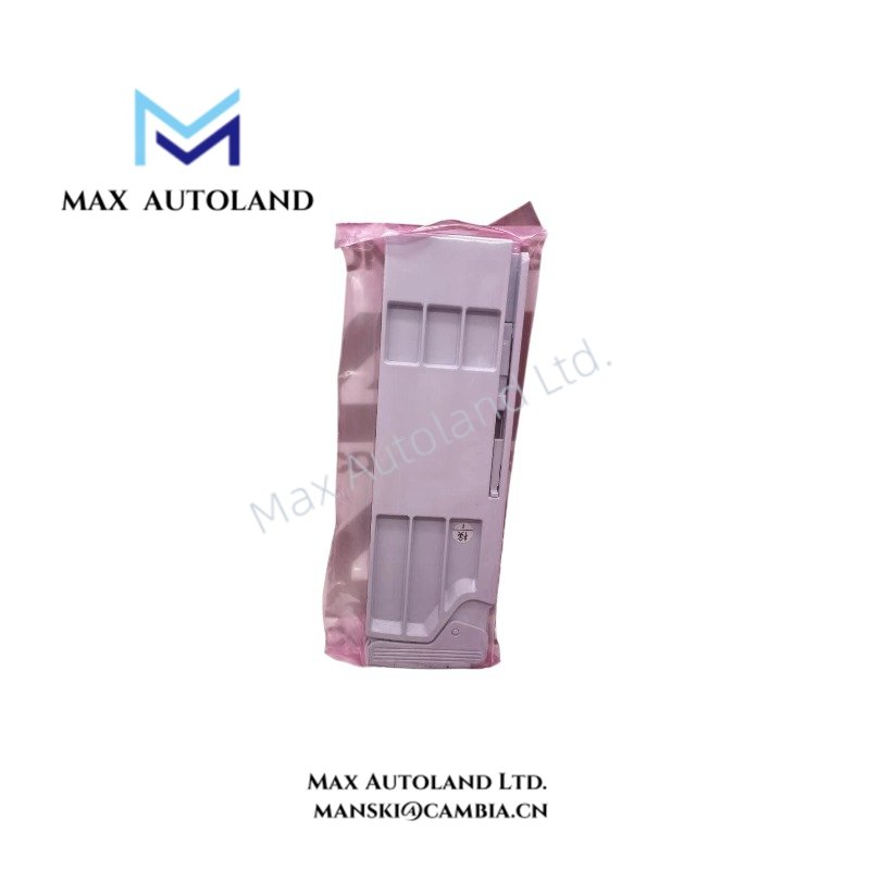
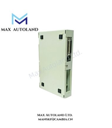
| Product Type | Current/Voltage Output Adaptor |
| Weight | 0.10 kg or less |
| Power Consumption | 24 VDC: 38 mA max; 5 VDC: 10 mA max |
| Voltage Output | 0 to 10 VDC |
| Voltage Output Range | -0.3 to 10.3 VDC |
| Current Output | 4-20 mA DC |
| Current Output Range | 1 to 23 mA DC |
| Voltage Output Load Resistance | 10 kOhm or higher |
| Current Output Load Resistance | 0 to 750 Ohm at 20 mA; 0 to 600 Ohm at 23 mA |
| Voltage Output Resistance | 1 Ohm or lower |
| Withstanding Voltage | Output signal to system: 1500 VAC for 1 minute |
| Inter-adaptor Withstanding Voltage | 500 VAC for 1 minute |
| Mounting Method | Dedicated A2BN3D Base Plate for Adaptor |
| System Compatibility | Yokogawa CENTUM VP N-IO |
| Compatible I/O Module Requirement | A2MMM843 style 2 or later |
Analog Output Signal Conditioning and Electrical Isolation
The A2SAM505-H000 S1 provides configurable analog output interfacing for voltage and current signals. Consequently, the control system can transmit output commands to compatible field devices using the specified signal ranges.
The output characteristics include:
- Voltage mode: 0 to 10 VDC, with an allowable output range of -0.3 to 10.3 VDC.
- Current mode: 4-20 mA DC, with an allowable output range of 1 to 23 mA DC.
- Voltage load: Requires a load resistance of 10 kOhm or higher.
- Current load: Supports 750 Ohm maximum at 20 mA and 600 Ohm maximum at 23 mA.
- Electrical separation: Withstands 1500 VAC between output signals and the system for 1 minute, and 500 VAC between I/O adaptors for 1 minute.
These specifications define the electrical operating limits for the adaptor and its connected output circuits. However, the supplied data does not specify channel count, output accuracy, or conversion resolution.
Frequently Asked Questions (FAQ)
Q: Which output signal types does the Yokogawa A2SAM505-H000 S1 support?
A: The adaptor supports configurable voltage output from 0 to 10 VDC and current output from 4-20 mA DC. The specified extended output ranges are -0.3 to 10.3 VDC and 1 to 23 mA DC, respectively.
Q: What load resistance is required for the current and voltage outputs?
A: Voltage output requires a load resistance of 10 kOhm or higher. Current output supports loads up to 750 Ohm at 20 mA or 600 Ohm at 23 mA.
Q: Which mounting base and I/O modules are compatible with this adaptor?
A: The A2SAM505-H000 S1 mounts on the dedicated A2BN3D Base Plate for Adaptor. The specified system compatibility includes CENTUM VP N-IO with compatible A2MMM843 style 2 or later I/O modules.
Field Installation Guidelines
1. Mounting: Install the A2SAM505-H000 S1 on the dedicated A2BN3D Base Plate for Adaptor. Verify mechanical alignment and secure engagement before connecting field wiring.
2. System compatibility: Confirm that the target CENTUM VP N-IO configuration supports the adaptor and the specified A2MMM843 style 2 or later I/O module.
3. Signal configuration: Select the required voltage or current output mode through the applicable system configuration. Verify that the connected field device accepts the selected signal range.
4. Load verification: Check the connected load resistance against the specified limits. For voltage output, maintain at least 10 kOhm. For current output, observe the applicable maximum resistance at the operating current.
5. Wiring: Route analog output conductors separately from high-current power wiring where practical. Use appropriate cable shielding and grounding practices according to the system installation documentation.
6. Power supply: Verify the availability of the specified 24 VDC system supply and 5 VDC internal supply. Account for the maximum stated current consumption when checking the applicable power budget.
7. Electrical isolation: Observe the specified withstand voltage limits during system design and electrical testing. Do not apply insulation test voltages beyond the documented ratings.
8. Commissioning: Before connecting field actuators, verify wiring polarity, output mode, load resistance, and the expected output signal using the approved commissioning procedure.
YOKOGAWA Top Products
| CPU | Power Supply and Battery | Rack |
| SCP451-51 | S9562FA | A1BD5D-06 |
| CP461-10 S1 | S9564FA | A1BR4D-05 |
| CP330D S3 | S9345FA | AKB337-M020 |
| CP461-50 S2 | S9548FA | NFBU200-015 |
| SCP451-53 | S9260DE-01 | NFBU200-S10 |
| SCP401-11 | S9971DB-0 | SNT411-13 |
| S2CP471-01 | S9681DB | SED2D-01 |
| CP451-51 | S9841DA | NFAF135-S00 |
| CP471-01 | SPW484-53 | NFAI835-S50 |
| CP461-53 | NFPW442-50 | NFAI543-H00 |
Customers Also Viewed
| Bently Nevada | ABB | GE Fanuc | Honeywell | Invensys |
|---|---|---|---|---|
| 330101-00-40-05-02-00 | PM591-2ETH | IS200ECTBG2A | CC-TDIL11 | FBM223 |
| 330101-00-40-10-02-00 | PM595-4ETH-F | IS200EPCTG1AZZ | CC-IP0101 | FBM207b |
| 330101-00-40-10-02-05 | DX522 | IS200VRTDH1DAA | CC-PAIX01 | FBM206 |
| 330101-00-43-15-02-05 | AX521 | IS200ERIOH1ACB | CC-TCNT01 | FBM237 |
| 330101-00-52-15-02-05 | AX522 | IS200ERQCH1A | CC-TAOX01 | FBM217 |
| 330101-00-55-05-02-05 | DI524 | IS200EACFG1BAA | CC-PDIS01 | FBM215 |
| 330101-00-55-10-02-05 | DI561 | IS200TVIBH2B | CC-PAIX01 | FBM211 |
| 330101-00-67-10-12-CN | DI562 | IS415UCVGH1A | CC-PAIH01 | FBM207 |
| 330101-00-75-15-02-05 | DI571 | IS200JPDDG1AAA | CC-PUIO31 | FBM223 |
| 330101-00-79-15-02-05 | DI581-S | IS200SPROH1ADD | CC-TAIX51 | FBM231 |



Reviews
There are no reviews yet.