
Overview
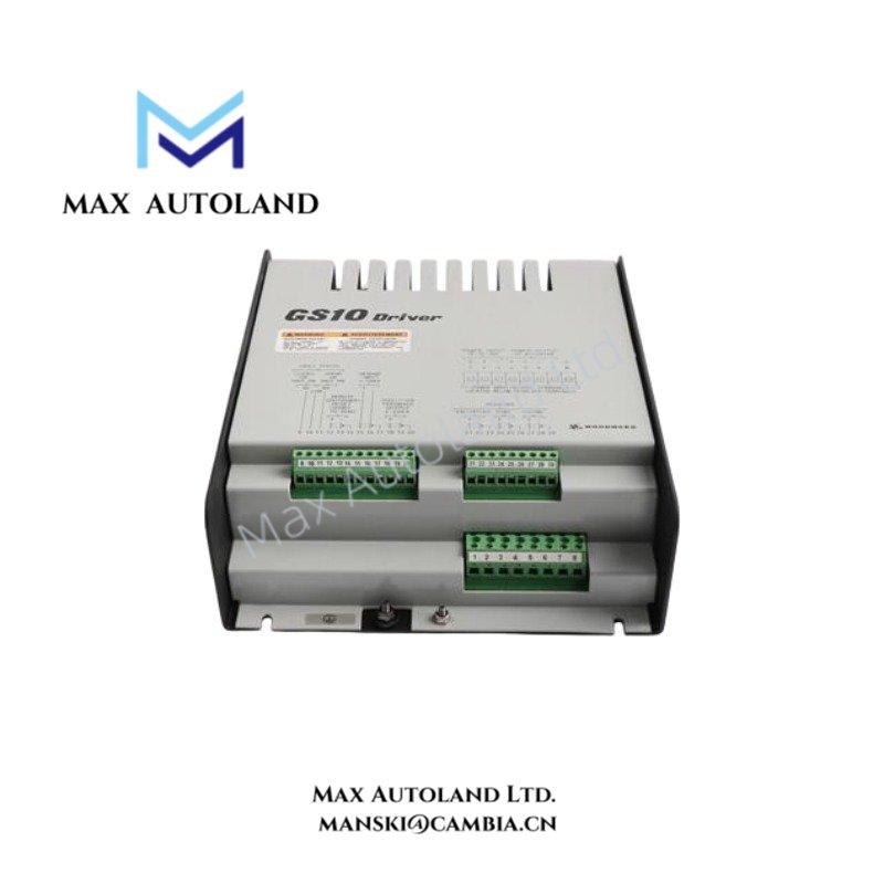
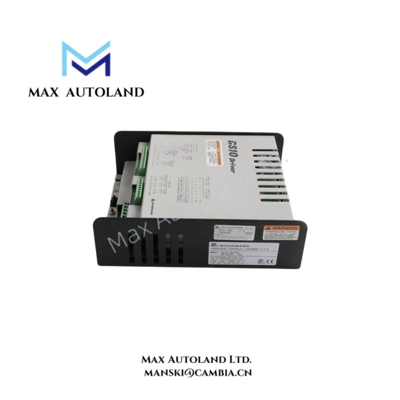
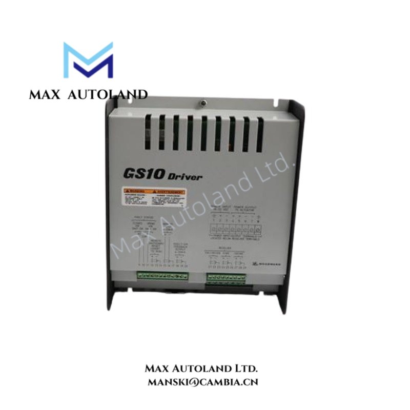
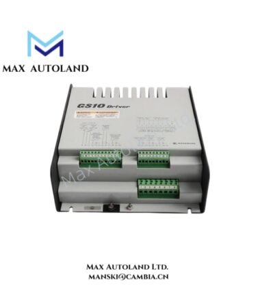
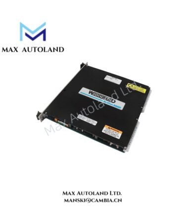
The Woodward 9907-186, also identified by the base model 9907-186, is a GS10 valve driver control unit that processes 4-20 mA position commands and provides an isolated 4-20 mA position feedback signal. It operates with an 18 to 32 VDC supply and controls the connected drive circuit according to the configured system requirements.
Hardware Specifications
| Parameter | Specification |
|---|---|
| Model | 9907-186 |
| Brand | Woodward |
| Product Type | GS10 Valve Driver Control Unit |
| Operating Temp | -20 to +55 deg C |
| Power Consumption | Not specified; steady-state current: 4 A |
| Supply Voltage | 18 to 32 VDC |
| Steady-State Current | 4 A |
| Peak Current | 20 A for 50 ms |
| Secondary Peak Current | 10 A for 500 ms |
| Position Command | 4-20 mA |
| Position Feedback | Isolated 4-20 mA output |
| Signal Isolation | 500 VDC |
| Feedback Accuracy | +/-0.2 mA or 1.25% |
| Fault Relay Rating | 2 A at 28 VDC, resistive load |
| Remote Reset Current | 10 to 20 mA |
| Maximum Interconnect Length | Less than 100 m |
| Drive Power Wiring | Four 3 mm2 conductors |
| Coil Resistance | 0.28 ohm +/-10% at 20 deg C |
| Coil Inductance | 40 mH at 60 Hz |
Actuator Loop Feedback and Drive Current Characteristics
The 9907-186 uses a 4-20 mA position command for the configured drive function. Its isolated 4-20 mA feedback output provides a corresponding electrical signal for position monitoring. The specified feedback accuracy is +/-0.2 mA or 1.25%.
The power section supports a steady-state current of 4 A, a peak current of 20 A for 50 ms, and a secondary peak current of 10 A for 500 ms. These current ratings describe different operating conditions and should not be treated as continuous output ratings.
The specified coil resistance is 0.28 ohm +/-10% at 20 deg C, with an inductance of 40 mH at 60 Hz. These parameters are relevant when checking actuator compatibility and evaluating the electrical characteristics of the connected load.
Frequently Asked Questions
Q: What supply voltage does the Woodward 9907-186 require?
A: The specified supply voltage range is 18 to 32 VDC. Verify the actual supply polarity and wiring against the manufacturer’s connection documentation before energizing the unit.
Q: What position command and feedback signals does this unit support?
A: The unit accepts a 4-20 mA position command and provides an isolated 4-20 mA position feedback output. The specified signal isolation is 500 VDC.
Q: What wiring limits apply to the drive circuit?
A: The specified drive power wiring uses four 3 mm2 conductors. The maximum interconnect length is less than 100 m. Confirm the terminal assignments, conductor requirements, shielding, and grounding arrangements against the applicable wiring diagram.
Field Installation Guidelines
- Verify the hardware: Confirm the complete model number, terminal identification, and compatibility with the installed Woodward GS10 system before replacement or commissioning.
- Check the power supply: Ensure that the DC supply remains within the specified 18 to 32 VDC range under the expected operating load.
- Inspect drive wiring: Use conductors that meet the specified four-conductor, 3 mm2 drive power wiring requirement. Verify terminal tightness and conductor routing against the manufacturer’s documentation.
- Separate signal and power wiring: Route the 4-20 mA command and feedback circuits separately from high-current drive wiring where practical. Apply the manufacturer’s shielding and grounding requirements to minimize electrical interference.
- Verify actuator compatibility: Compare the connected coil’s resistance and inductance with the documented values of 0.28 ohm +/-10% at 20 deg C and 40 mH at 60 Hz. Confirm compatibility with the complete drive circuit before applying power.
- Check interconnect length: Keep the relevant interconnect within the specified limit of less than 100 m. Verify any additional cable restrictions in the system documentation.
- Perform commissioning checks: Before enabling the drive, inspect the command and feedback loops, confirm the fault relay wiring, and verify the configured remote reset circuit. Test the response under the approved commissioning procedure.





Reviews
There are no reviews yet.