




Overview
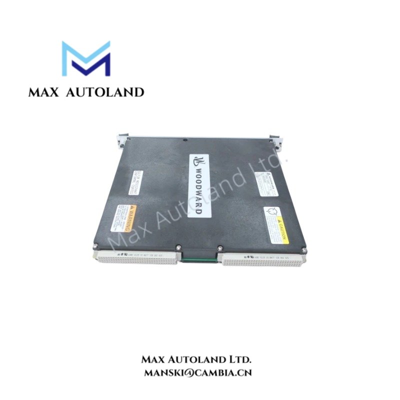
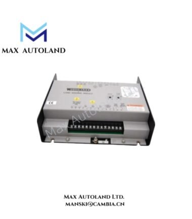
The Woodward 5466-1049, also identified by the base model 5466-1049, is a kernel power supply module for the Woodward MicroNet TMR Plus control system. It supplies power to kernel-level control hardware. The provided specifications list a 24 VDC input and a 5 VDC output. Confirm the electrical ratings and chassis compatibility against the applicable Woodward hardware documentation before installation.
Hardware Specifications
| Parameter | Specification |
|---|---|
| Model | 5466-1049 |
| Brand | Woodward |
| Series | MicroNet TMR Plus |
| Module Type | Kernel Power Supply Module |
| Weight | Approximately 22 kg when installed in chassis |
| Operating Temp | 0 deg C to +55 deg C |
| Storage Temp | -40 deg C to +105 deg C |
| Input Voltage | 24 VDC, +/-10% |
| Output Voltage | 5 VDC, +/-5% |
| Associated Manuals | Woodward 26167V1 and 26166V2 |
Governor Power Distribution and Electrical Integration
The 5466-1049 belongs to the Woodward MicroNet TMR Plus control platform. Its stated function is to provide power to kernel-level control hardware.
For electrical integration, verify the input supply range, output voltage tolerance, connector pin assignments, grounding arrangement, and permitted load against the system documentation. Do not assume that the module supports hot swapping or independent redundant operation without confirmation from the applicable manual.
Frequently Asked Questions
Q: What input voltage does the Woodward 5466-1049 use?
A: The supplied specifications state 24 VDC with a tolerance of +/-10%. Verify this rating against the applicable Woodward manual before energizing the module.
Q: What output voltage is specified for this module?
A: The supplied data lists 5 VDC with a tolerance of +/-5%. The rated output current and maximum power capacity have not been provided.
Q: Can the 5466-1049 be replaced while the control system is operating?
A: Hot-swap capability is not confirmed by the available information. Check the MicroNet TMR Plus maintenance procedure and system configuration before removing or replacing the module.
Field Installation Guidelines
- Verify the complete part number and hardware revision against the installed MicroNet TMR Plus system documentation.
- Isolate the relevant power source and follow the manufacturer’s approved maintenance and electrical safety procedures.
- Confirm the input voltage, connector assignments, polarity, and output load requirements before connection.
- Inspect the module connector and chassis slot for contamination, bent contacts, or mechanical damage.
- Route power wiring separately from low-level analog signals and sensitive communication cables where practical.
- Apply the grounding and bonding arrangement specified by Woodward. Do not introduce additional shield-ground connections without reviewing the system grounding design.
- After installation, verify supply voltage, module status indicators, and control-system diagnostics before returning the equipment to service.






Reviews
There are no reviews yet.