
Overview
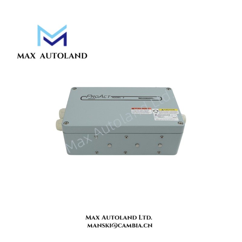
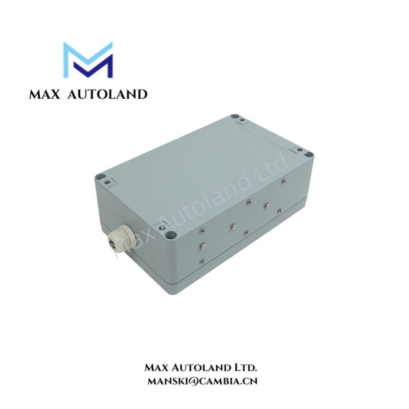
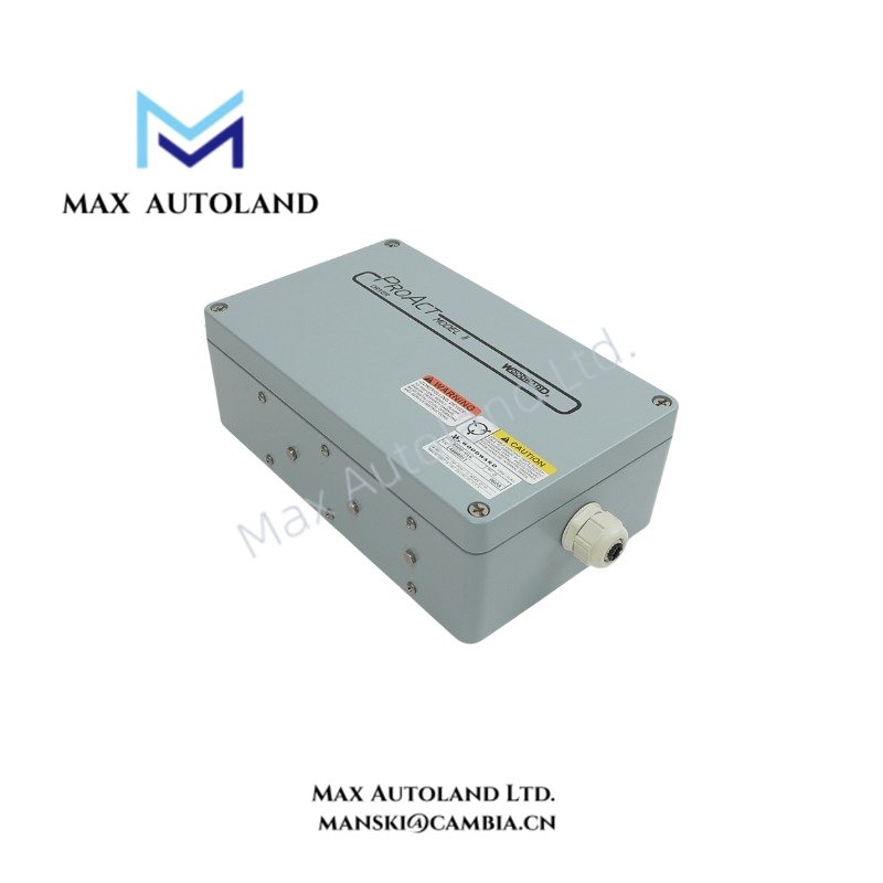
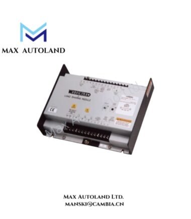
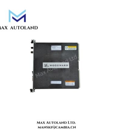
The WOODWARD 8400-016, also cataloged as the 8400-016 Speed Control Proact Module, operates as a dedicated hardware component for precise fuel valve actuation and closed-loop speed regulation within industrial engine management networks.
Hardware Specifications
| Parameter | Specification |
|---|---|
| Model | 8400-016 |
| Brand | Woodward |
| Origin | USA |
| Weight | 2.75 kg |
| Dimensions | 31 x 16 x 9 cm |
| Operating Temp | -40 deg C to +70 deg C |
| Power Consumption | 10 – 15 W |
| Supply Voltage | 24 VDC |
| Speed Range | 0 to 6000 rpm |
| Accuracy | +0.25% |
| Response Time | Less than 100 milliseconds |
| Analog Inputs | 4-20 mA |
| Digital Inputs | For start/stop |
| Analog Output | 4-20 mA |
| Storage Temperature | -40 deg C to +85 deg C |
| Relative Humidity | 5 – 95% RH (non-condensing) |
Actuator Loop Feedback Response and Thermal Management
The module executes high-frequency closed-loop corrections through an integrated 4-20 mA proportional feedback channel, maintaining dynamic stability under fluctuating load vectors. Actuator loop feedback response times remain under 100 milliseconds to suppress transient overspeed conditions across connected turbine systems. Thermal heat sink dissipation profiles are engineered to handle continuous dissipation loads at ambient temperatures reaching +70 deg C without internal electronic derating.
Frequently Asked Questions
Q: What is the maximum permissible cable length for the 4-20 mA analog control loops?
A: Shielded twisted-pair cabling should not exceed 300 meters to prevent signal attenuation and maintain loop impedance within specified operational thresholds.
Q: Does the module support hot-swapping under live 24 VDC supply conditions?
A: No. Power must be isolated prior to insertion or removal to prevent electrical arcing across interface pins and potential damage to internal solid-state components.
Q: How do the digital inputs process start and stop commands?
A: The digital inputs accept dry contact closures referenced to internal logic ground, triggering internal state transitions for engine sequencing routines.
Field Installation Guidelines
- Mount the module vertically on a rigid DIN rail or subplate within an industrial enclosure rated at least IP54 to protect against airborne contaminants and moisture ingress.
- Ensure all signal cable shields are terminated to the designated earth ground bar at a single point to eliminate electromagnetic interference (EMI) ground loops.
- Maintain a minimum vertical clearance of 50 mm above and below the housing enclosure to facilitate unrestricted convective airflow across thermal dissipation surfaces.



Reviews
There are no reviews yet.